Dear all,
In the course of my work with SUMO, I have encountered a few questions or issues with my network that I would like to ask for your clarification or support.
1)
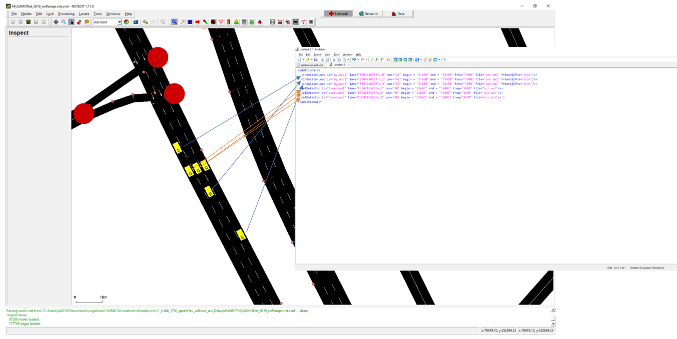
Question regarding the positioning of Induction Loops.
As you can see in the attachment (File: InductionLoop_1.PNG) I tried to position some Induction Loops on an edge in my network using NetEdit. Two Induction Loops were positioned on each lane of this edge.
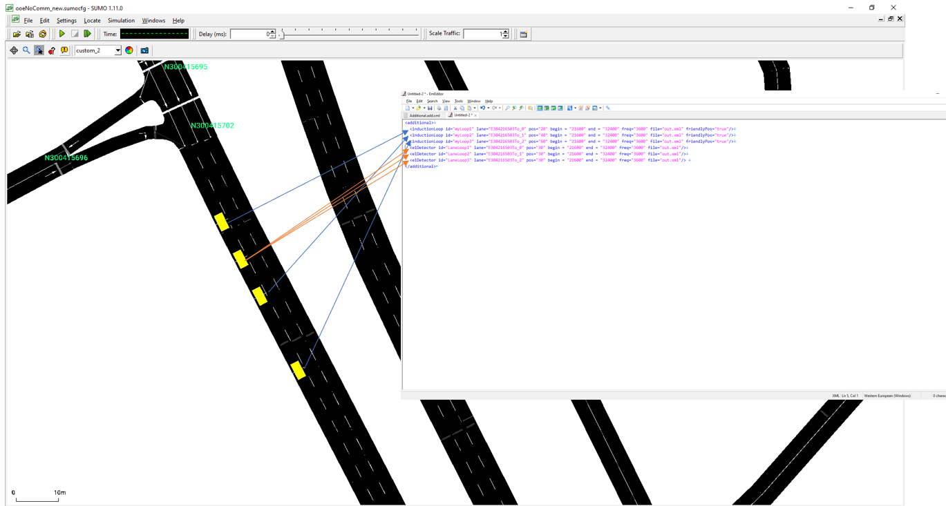
But when I load the network and the Additional File with the loops in the SUMO-Gui, all Induction Loops are placed on lane 0. (compare file InductionLoop_2.PNG), and the ouput for each of the loops after the end of the simulation is the
same/very similar.
Is it to be expected here that the placed induction loops, in contrast to what is drawn in NetEdit, are actually positioned only on one lane as seen in the SUMO GUI, and accordingly only record data from this lane? Or are the loops only
visually displayed on lane 0, and are all data of the edge counted, i.e. across all lanes?
2)
And the second question:
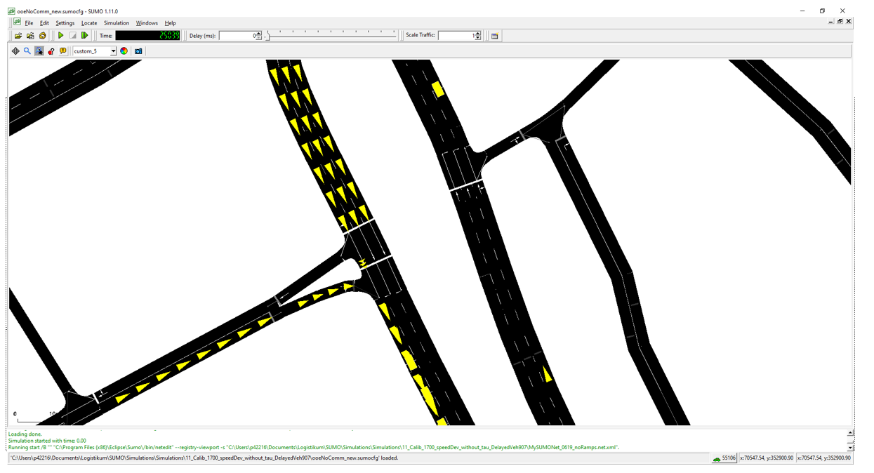
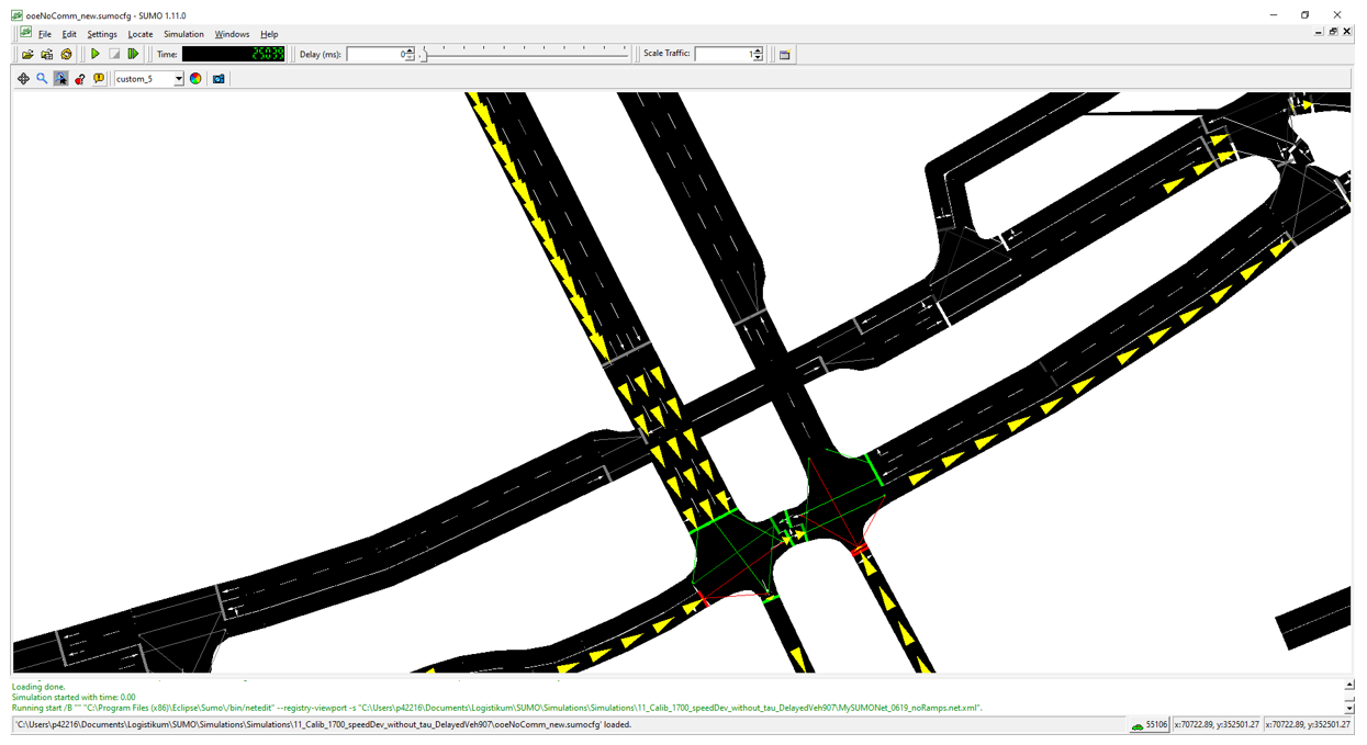
As you can see in the screenshot VehicleLaneChange_1.PNG I have the problem that the vehicles of a jammed edge all change to lane 0 of the next edge when crossing the junction. The exact opposite problem can be seen in the screenshot VehicleLaneChange_2.PNG
on the following edge and junction, since these vehicles on lane 0 are again divided among all three lanes of the following edge. The lane-to-lane connections have already been checked and are modeled correctly.
Could this be a visualization error in the GUI?
If I position Induction Loops on the two relevant edges from the screenshot VehicleLaneChange_2.PNG, I can see that the generated data is basically similar. This would then, if I again assume that the induction loops count the entire edge
across all lanes, only occur if all vehicles are by mistake displayed on lane 0 in the previous edge.
However, as described in the first question, I cannot position induction loops on lane 1, so I could not check whether a loop on the edge on which all vehicles are visualized on lane 0 would actually deliver no data.
Some additional info:
I use a meso model in my example, maybe that contributes to the described problems.
Thank you very much for your support and best regards,
Manuel Walch
Manuel Walch, BA, MSc
Research Associate
Logistikum –
Department of Logistics at the
University of Applied Sciences Upper Austria
FH OÖ Forschungs & Entwicklungs GmbH
Wehrgrabengasse 1-3
4400 Steyr/Austria
tel: +43 5 0804 33258
fax: +43 5 0804 33299
e-mail:
manuel.walch@xxxxxxxxxxx
web1:
www.logistikum.at
web2:
www.fh-ooe.at
Firmenbuchgericht/Court of registry: Landesgericht Wels
Firmenbuchnummer/Company registration: FN 236733 m
