VehicleComponents
AEB
The Autonomous Emergency Braking system checks if a collision is likely to occur in the near future and, if necessary, brakes to avoid the collision. In each timestep, the system evaluates all objects detected by a Sensor and calculates the time to collision (TTC) for this object based on the perceived movement of the object. If, for any object, the TTC is lower than the threshold of the component, then the component gets activated. The system deactivates if the TTC is larger than 1,5 times the threshold of the component.
Attribute |
Type |
Unit |
Description |
|---|---|---|---|
CollisionDetectionLongitudinalBoundary |
Double |
m |
Additional length added the vehicle boundary when checking for collision detection |
CollisionDetectionLateralBoundary |
Double |
m |
Additional width added the vehicle boundary when checking for collision detection |
TTC |
Double |
s |
Time to collision which is used to trigger AEB |
Acceleration |
Double |
m/s² |
Braking acceleration when activated |
<ProfileGroup Type="AEB">
    <Profile Type="AEB" Name="AEB1">
        <Double Key="CollisionDetectionLongitudinalBoundary" Value="4.0"/>
        <Double Key="CollisionDetectionLateralBoundary" Value="1.5"/>
        <Double Key="TTC" Value="2.0"/>
        <Double Key="Acceleration" Value="-2"/>
    </Profile>
    ...
</ProfileGroup>
DynamicsTrajectoryFollower
This module forces agents to drive according to a specific trajectory. The trajectory is defined in the scenario. This module is disabled by default and is activated if a trajectory from openSCENARIO is triggered. It is always important that the trajectories matches the current scenery file, otherwise the Agent could be placed outside of valid lanes. If the agent gets placed on a invalid position, it will be deleted.
All attributes are required.
Attribute |
Type |
Description |
|---|---|---|
AutomaticDeactivation |
Bool |
If true, the trajectory follower relinquishes control of the vehicle after the final instruction in the TrajectoryFile. If false, it stops at the last point of the trajectory. |
EnforceTrajectory |
Bool |
If true, the trajectory follower overrides external input related to the vehicle’s travel. |
<ProfileGroup Type="DynamicsTrajectoryFollower">
    <Profile Name="BasicTrajectoryFollower">
        <Bool Key="AutomaticDeactivation" Value="true"/>
        <Bool Key="EnforceTrajectory" Value="true"/>
    </Profile>
</ProfileGroup>
FMU Wrapper
The FMU Wrapper provides a connection to arbitrary FMUs (Functional Mock-up Unit). An FMU has to be compatible with the FMI 1.0 or the FMI 2.0 specification (Functional Mock-up Interface) and has to be ABI (Application Binary Interface) compatible with the opSimulation binary.
Additional reading about FMI is provided by the FMI standard website at https://fmi-standard.org/. For interfacing the FMUs in openPASS, the Modelon FMI Library is used, which is recommended on the FMI standard website. See https://jmodelica.org/.
FMU package format
FMI defines a packaging format for FMUs.
The used container format is ZIP.
It basically contains - among other parts - the compiled FMU code (as *.dll or *.so, depending on the platform) and the modelDescription.xml.
Latter provides meta-data about the FMU, i. e.
- Author information
- Model name, identifier and description
- Generation timestamp
- Name and datatype of model variables (inputs and outputs)
Architectural overview
The wrapper is instantiated as a component of an agent. It reads the input variables for the FMU from the simulation and provides it the FMU and reads the output of the FMU and forwards it via signals to other agent components.

Framework channels
The wrapper can use input and output signals via Channels as every other agent component does. Framework channels (signals) can provide data and can also be written to by the wrapper. In addition, the wrapper is able to access the c AgentInterface and c WorldInterface methods.
FMI variables
Communication with the FMU happens via FMI variables (inputs and outputs).
The wrapper will read in available variables from modelDescription.xml in the FMU package.
These variables need to be mapped to variables and signals of openPASS in the VehicleComponentProfile.
FMI 1.0 supports these standard datatypes: - bool - integer - real - string
By using OSMP, three integer values can be used to support full osi messages
Configuration
Configuration of a particular FMU takes place in ProfilesCatalog.xml.
An example of a static system configuration can be found here “sim/contrib/examples/Configurations/StaticOSMPSensorDataToTrafficUpdateStepper”.
The following parameters are always required for the FmuWrapper. Depending on the FmuHandler additional parameters may be needed.
Key |
Type |
Default |
Description |
|---|---|---|---|
FmuPath |
string |
- |
Path to FMU file, either absolute or relative to the simulator’s configuration directory. |
Logging |
bool |
true |
If set to true, FMU initialization and execution task are logged to a text file. |
CsvOutput |
bool |
true |
If set to true, FMI outputs are logged to a CSV file. |
<ProfileGroup Type="FMU1">
  <Profile Name="FMU">
    <String Key="FmuPath" Value="OSMPSDToTUS.fmu"/>
    <Bool Key="Logging" Value="true"/>
    <Bool Key="CsvOutput" Value="false"/>
    <String Key="Input_OSMPSensorDataIn" Value="SensorData"/>
    <String Key="Output_OSMPTrafficUpdateOut" Value="TrafficUpdate"/>
 <Bool Key="WriteJson_SensorData" Value="false"/>
 <Bool Key="WriteJson_TrafficUpdate" Value="false"/>
  </Profile>
</ProfileGroup>
Upon instantiation of the FMU wrapper, it will extract the FMU ZIP file to a temporary directory.
Then the modelDescription.xml is parsed and the FMU is checked for compatibility.
If the parameter CsvOutput is set to true, a subfolder “FmuWrapper/Agent<ID>” will be created in the simulator’s “results” directory.
“<ID>” is replaced with the agent id.
FMI output data will be logged to a file inside this directory.
The filename consists of the FMU’s name and extension “csv”.
This output can then be used for visualization in a spreadsheet application or it may be processed in any other way.
Same goes for parameter Logging (having “log” as output file extension).
Primitive Datatypes
The FMU Wrapper allows to link Simulink models or any other FMU to openPASS. It lets the user link any input variables of the FMU to values of the Agent in the simulation and any output values of the FMU to signals, that are forwarded to other openPASS components. These mappings are defined with the following optional parameters.
Note
Be careful with the size of integer data types when used in Matlab/Simulink. The FMU integer data type shall always be 32 bit or bigger, e.g. for IDs.
Key |
Type |
Description |
|---|---|---|
Parameter_varName |
any |
Mapping of a fixed value (bool, integer, double, string) to an FMU input:
|
Parameter_AssignSpecial_varName |
any |
Mapping of a specific value of the simulation to an FMU input, assigned only once at FMU initialization:
|
Input_varName |
string |
Mapping of a specific value of the simulation to an FMU input:
|
Output_varName |
string |
Mapping of a FMU output to a specific field in a specific signal:
|
The allowed special simulation values are as follows:
Type |
FMU Variable Type |
Calculation |
|---|---|---|
RandomSeed |
Integer |
The random seed of the current simulation run. |
OutputPath |
String |
An output path unique to this FmuWrapper instance. The path will always refer to a directory below the simulator’s current result folder. This directory is not necessarily created by the FmuWrapper, depending on the setting of CsvOutput and Logging parameters (see FmuWrapper basic configuration). |
MaxSteering |
Real |
The max_steering property of an agent’s front axle as defined in OpenSCENARIO (catalog). |
SteeringRatio |
Real |
The steering ratio of the vehicle model.
Has to be defined in the properties of the Entity in the OpenSCENARIO catalog with the name
|
NumberOfGears |
Integer |
The number of gears of the vehicle model.
Has to be defined in the properties of the Entity in the OpenSCENARIO catalog with the name
|
GearRatioN |
Real |
The ratio of the Nth gear.
Has to be defined in the properties of the Entity in the OpenSCENARIO catalog with the name
|
The allowed inputs (simulation values) are as follows:
Type |
FMU Variable Type |
Calculation |
|---|---|---|
VelocityEgo |
Real |
Absolute velocity (length of the velocity vector) at reference point |
AccelerationEgo |
Real |
Longitudinal acceleration at reference point |
CentripetalAccelerationEgo |
Real |
Centripetal acceleration at reference point |
SteeringWheelEgo |
Real |
Angle of the steering wheel (in radian) |
AccelerationPedalPositionEgo |
Real |
Position of the acceleration pedal in the interval [0, 1] |
BrakePedalPositionEgo |
Real |
Position of the brake pedal in the interval [0, 1] |
DistanceRefToFrontEdgeEgo |
Real |
Distance between the reference point and the front of the agent (static) |
PositionXEgo |
Real |
X position of the reference point |
PositionYEgo |
Real |
Y position of the reference point |
YawEgo |
Real |
Yaw of the reference point |
LaneEgo |
Integer |
Lane id of the front center on the route (0, if off route) |
PositionSEgo |
Real |
S position of the reference point on the route (0, if off route) |
PositionTEgo |
Real |
T position of the reference point on the route (0, if off route) |
ExistenceFront |
Boolean |
true, if there is a object in front on the own lane (any range), false otherwise |
PositionXFront |
Real |
X position of front object reference point (0, if no front object) |
PositionYFront |
Real |
Y position of front object reference point (0, if no front object) |
YawFront |
Real |
Yaw of front object reference point (0, if no front object) |
PositionSFront |
Real |
S position of front object reference point on ego route (0, if no front object) |
PositionTFront |
Real |
T position of front object reference point on ego route (0, if no front object) |
RelativeDistanceFront |
Real |
Net distance to front object along route (0, if no front object) |
WidthFront |
Real |
Width of front object (0, if no front object) |
LengthFront |
Real |
Length of front object (0, if no front object) |
DistanceRefToFrontEdgeFront |
Real |
Distance between the reference point and the front of the front object (0, if no front object) |
VelocityFront |
Real |
Absolute velocity of front object at reference point (0, if no front object) |
LaneFront |
Integer |
Lane id of the reference point of the front object on the ego route (0, if no front object) |
ExistenceFrontFront |
Boolean |
true, if there are at least two objects in front on the own lane (any range), false otherwise |
PositionXFrontFront |
Real |
X position of second front object reference point (0, if no second front object) |
PositionYFrontFront |
Real |
Y position of second front object reference point (0, if no second front object) |
RelativeDistanceFrontFront |
Real |
Net distance to second front object reference point (0, if no second front object) |
VelocityFrontFront |
Real |
Absolute velocity of second front object reference point (0, if no second front object) |
LaneFrontFront |
Integer |
Lane id of the reference point of second front object reference point (0, if no second front object) |
LaneCountLeft |
Integer |
Number of lanes to the left of front center of type Driving, Exit, Entry, OnRamp or OffRamp |
LaneCountRight |
Integer |
Number of lanes to the right of front center of type Driving, Exit, Entry, OnRamp or OffRamp |
SpeedLimit_X |
Real |
Speed limit in effect in distance X meters from front center (999, if no speed limit) |
RoadCurvature_X |
Real |
Road curvature in distance X meters from front center |
reference point: Center of the rear axle
front center: Center of the front of the bounding box of the object
If the FmuWrapper is linked to at least one sensor with InputId “Camera”, the following additional inputs are available. The objects seen by this sensor(s) are sorted by distance from the agent and accessed by indices starting from 0. For each object the values listed in the following table are available where X is the index of the object (between 0 and 9). If there are less objects than X, a default value is set (-1 for the Id, 0 for the other values). Only the list of objects is taken from the sensor. The values are then calculated by the FmuWrapper (not from the SensorData).
Type |
FMU Variable Type |
Calculation |
|---|---|---|
SensorFusionObjectId_X |
Integer |
Id of the object |
SensorFusionNumberOfDetectingSensors_X |
Integer |
Number of sensors detecting the object |
SensorFusionRelativeS_X |
Real |
Distance between reference points along route (NaN, if object not on route) |
SensorFusionRelativeNetS_X |
Real |
Net distance along route (NaN, if object not on route) |
SensorFusionRelativeT_X |
Real |
Lateral obstruction for front center (NaN, if object not on route) (see GetObstruction) |
SensorFusionRelativeX_X |
Real |
Relative distance between reference points in x in world coordinates |
SensorFusionRelativeY_X |
Real |
Relative distance between reference points in y in world coordinates |
SensorFusionRelativeNetLeft_X |
Real |
Lateral obstruction for leftmost point (NaN, if object not on route) |
SensorFusionRelativeNetRight_X |
Real |
Lateral obstruction for rightmost point (NaN, if object not on route) |
SensorFusionRelativeNetX_X |
Real |
Net distance between bounding boxes in x in world coordinates |
SensorFusionRelativeNetY_X |
Real |
Net distance between bounding boxes in y in world coordinates |
SensorFusionLane_X |
Integer |
Lane of front center |
SensorFusionVelocity_X |
Real |
Absolute velocity at reference point |
SensorFusionVelocityX_X |
Real |
Velocity in x at reference point in world coordinates |
SensorFusionVelocityY_X |
Real |
Velocity in y at reference point in world coordinates |
SensorFusionYaw_X |
Real |
Yaw in world coordinates |
The FMU wrapper can output one or more of these signals: AccelerationSignal, LongitudinalSignal, SteeringSignal and DynamicsSignal
The name of the signal field has to be specified after the signal name. This means the output type is one of the following:
Type |
FMU Variable Type |
Enum Values |
|---|---|---|
ComponentState |
Enum |
Undefined, Disabled, Armed, Acting |
AccelerationSignal_Acceleration |
Real |
|
LongitudinalSignal_AccPedalPos |
Real |
|
LongitudinalSignal_BrakePedalPos |
Real |
|
LongitudinalSignal_Gear |
Int |
|
SteeringSignal_SteeringWheelAngle |
Real |
|
DynamicsSignal_Acceleration |
Real |
|
DynamicsSignal_Velocity |
Real |
|
DynamicsSignal_PositionX |
Real |
|
DynamicsSignal_PositionY |
Real |
|
DynamicsSignal_Yaw |
Real |
|
DynamicsSignal_YawRate |
Real |
|
DynamicsSignal_YawAcceleration |
Real |
|
DynamicsSignal_SteeringWheelAngle |
Real |
|
DynamicsSignal_CentripetalAcceleration |
Real |
|
DynamicsSignal_TravelDistance |
Real |
|
CompCtrlSignal_MovementDomain |
Enum |
Undefined, Lateral, Longitudinal, Both |
CompCtrlSignal_WarningActivity |
Bool |
|
CompCtrlSignal_WarningLevel |
Enum |
INFO, WARNING |
CompCtrlSignal_WarningType |
Enum |
OPTIC, ACOUSTIC, HAPTIC |
CompCtrlSignal_WarningIntensity |
Enum |
LOW, MEDIUM, HIGH |
CompCtrlSignal_WarningDirection |
Enum |
If one of these fields of a signal (except ComponentState) is mapped to an FMU variable, all fields of this signal have to be mapped. If the ComponentState is mapped to a FMU variable, it is used for all signals, otherwise it defaults to Acting.
OSI Data
OSMP (OsiSensorModelPackaging) is a package layer specification for the Open Simulation Interface (OSI). It allows to pass input to the FMU as OSI messages as well as receive output as OSI message. For more information on OSMP see https://github.com/OpenSimulationInterface/osi-sensor-model-packaging.
The FmuHandler has the following additional (optional) parameters:
Key |
Type |
Description |
|---|---|---|
Init_var_name |
string |
var_name references an FMU variable (as defined in FMU’s modelDescription.xml) to which a specific OSI message is sent during initialization Allowed values: GroundTruth |
Input_var_name |
string |
var_name references an FMU variable (as defined in FMU’s modelDescription.xml) to which a specific OSI message is sent Allowed values: SensorView, SensorViewConfig, SensorData, TrafficCommand |
Output_var_name |
string |
var_name references an FMU variable (as defined in FMU’s modelDescription.xml) from which a specific OSI message is received Allowed values: SensorViewConfigRequest, SensorData, TrafficUpdate |
Parameter_var_name |
any |
The value of the parameter is assigned to the FMU variable var_name |
Parameter_transformation[mapping ]_name |
string/string/any* |
Same as Parameter_name but with an preceding transformation according to a mapping. |
WriteJson_var_name |
bool |
If true the osi message specified by var_name is written to a json file |
WriteTrace_var_name |
bool |
If true the osi message specified by var_name is written to the trace file |
EnforceDoubleBuffering |
bool |
If true the wrapper will throw an error if FMU doesn’t use double buffering. Defaults to false. |
The type of OSI messages the FmuHandler sends and receives is defined by its parameters. Only messages for which an FMU variable is given in the configuration are sent/received. An additional parameter defines whether the message should be logged as JSON file for every agent and every timestep (see table above).
Currently these messages are supported:
SensorView: SensorView generated from the GroundTruth with this agent is host vehicle.
SensorViewConfig, SensorViewConfigRequest: Configuration of a sensor according to OSMP.
TrafficCommand: Trajectory from openSCENARIO, that will be converted into a TrafficCommand.
SensorData: Output of a sensor. Can be input and/or output of an FMU. Received SensorData is forwarded to other components as SensorDataSignal.
TrafficUpdate: Will be converted to a DynamicsSignal.
GroundTruth: Will be used as groundtruth information for everything that exists in the simulation world.
FmuVariables
FmuVariables can have different variability and causality.
There are the following causalities: Input, Output, Parameter and CalculatedParameter
Input or outputs can have the variability constant, fixed, discrete or continuous
Parameter or CalculatedParameter can have the variability constant, fixed or tunable
In openPASS we have the initialization phase, which is only called once. In that phase first readValues is called. Then parameter values are synchronized between different config files. The following priority is used for the synchronization:
modelDescription < systemConfig
Afterwards still in the initialization phase writeValues is called. During the whole simulation in openPASS all the trigger functions are called each time step. For the FMU component we call WriteValues before trigger and readValues afterwards. For the first two time steps we have the following calls for read- and writeValues:
ReadValues (Init)
WriteValues (Init)
WriteValues
Trigger
ReadValues
WriteValues
Trigger
ReadValues
Depending on them, FmuVariables are written/read to/from the FMU on different occasions, which is shown in the following table.
ReadValues - Init |
WriteValues - Init |
WriteValues - Trigger |
ReadValues - Trigger |
|
|---|---|---|---|---|
Input - fixed |
x |
x |
||
Input - discrete or continuous |
x |
x |
x |
|
Output - fixed |
x |
|||
Output - discrete or continuous |
x |
x |
||
Parameter - fixed |
x |
x |
||
Parameter - tunable |
x |
x |
x |
|
CalculatedParameter - fixed |
x |
|||
CalculatedParameter - tunable |
x |
x |
Note
For alle kinds of Input, Output, Parameter and CalculatedParameter there exists the variablity “constant”. All constant values are only read into openPASS once at the initialization phase. Never will these values be written onto the FMU.
SensorGeometric2D
This sensor is selected, when a sensor is parameterized as ProfileGroup “Geometric2D”.
Parameter |
Type |
Unit |
Description |
|---|---|---|---|
DetectionRange |
Double |
m |
Detection range |
EnableVisualObstruction |
Bool |
Activates 2D sensor obstruction calculation |
|
FailureProbability |
Double |
Probability object is not detected although it is visible |
|
Latency |
Double |
s |
Delay the sensor output |
DetectionDelayTime |
Double |
s |
Time an object needs to be in detection range before it is detected (optional) |
MaxDropOutTime |
Double |
s |
Time after which delay for undetected object starts anew (optional) |
OpeningAngleH |
Double |
rad |
Horizontal opening angle |
RequiredPercentageOfVisibleArea |
Double |
Required percentage of an object within the sensor cone to trigger a detection |
<ProfileGroup Type="Geometric2D">
  <Profile Name="Standard">
    <Double Key="DetectionRange" Value="300"/>
    <Bool Key="EnableVisualObstruction" Value="false"/>
    <Double Key="FailureProbability" Value="0"/>
    <NormalDistribution Key="Latency" Max="0.0" Mean="0.0" Min="0.0" SD="0.0"/>
    <Double Key="OpeningAngleH" Value="0.35"/>
    <Double Key="RequiredPercentageOfVisibleArea" Value="0.001"/>
    <Double Key="DetectionDelayTime" Value="0"/>
    <Double Key="MaxDropOutTime" Value="0"/>
  </Profile>
</ProfileGroup>
Note
Sensors also need a mounting position, defined w.r.t. the coordinate system of the vehicle (center of rear axis). See also VehicleProfiles.
ReceiverCar2X
This type is selected, when a sensor is parameterized as ProfileGroup “ReceiverCar2X”.
Parameter |
Type |
Unit |
Description |
|---|---|---|---|
FailureProbability |
Double |
Probability object is not detected although it is visible |
|
Latency |
Double |
s |
Sensor latency |
Sensitivity |
Double |
W/m² |
Sensitivity of the sensor |
<ProfileGroup Type="ReceiverCar2X">
  <Profile Name="Standard">
    <NormalDistribution Key="Latency" Mean="0.0" SD="0.0" Min="0.0" Max="0.0"/>
    <Double Key="FailureProbability" Value="0"/>
    <Double Key="Sensitivity" Value="1e-5"/>
  </Profile>
</ProfileGroup>
The moving object is detected if the received SignalStrength is greater than the Sensitivity of the ReceiverCar2X .
The received SignalStrength is calculated by 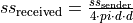 , where the symbols meanings are:
Symbol |
Description |
|---|---|
|
Received strength of the signal [1/m²] |
|
Sent strength of the signal [1/m²] |
|
Distance between the receiver agent and sender [m] |


Note
Sensors also need a mounting position, defined w.r.t. the coordinate system of the vehicle (center of rear axis). See also VehicleProfiles.
VehicleDynamics
Components of this group can be used to model the vehicle dynamics. The vehicle dynamics model has a modular design. If necessary, the individual components can be replaced by the user with their own models. The vehicle dynamics model consists of six components listed below:
Component |
Short Description |
|---|---|
The steering model transfers the driver’s input into the vehicle’s wheel angle |
|
The powertrain model converts the accelerator pedal position into wheel drive torques, under consideration of the selected gear |
|
The brake model converts the brake pedal position into wheel brake torques |
|
The tire model converts the predetermined drive and braking torques of the tires into tire longitudinal and lateral forces, under consideration of the wheel angles |
|
The motion model calculates the translational and rotational vehicle movement with the calculated tire forces |
|
The chassis model determines the dynamic wheel loads via the vehicle’s longitudinal and lateral acceleration |
The following figure gives an overview of the driving dynamics components and their signals:

ActionSteeringSystem
The steering model obtains the “SteeringRatio” property from the VehicleCatalog and uses it to calculate the steering angle of the front wheels. Both wheels are turned at the same angle. Steering elasticities are currently not taken into account. The following parameter can be used to set a static toe:
Attribute |
Type |
Unit |
Description |
|---|---|---|---|
StaticToe |
VectorDouble |
rad |
Static toe of the wheels (A positive value corresponds to a toe-in; wheels are indexed from the front left in the vector) |
ActionPowertrain
The powertrain model contains an engine model and a gear model. The type of the powertrain can be set using the following parameters:
Attribute |
Type |
Unit |
Description |
|---|---|---|---|
TypeDrivetrain |
String |
Type of drivetrain; A selection can be made between front-wheel drive (FWD), rear-wheel drive (RWD) and all-wheel drive (AWD) |
|
FrontRatioAWD |
Double |
Distribution of the drive torque to the front axle in the case of all-wheel drive (AWD); Range 0-1 |
The wheel speed is converted into an engine speed [Hz] according to the axle ratio and the transmission ratio of the selected gear. The axle ratio and gear ratios are obtained from the VehicleCatalog (“AxleRatio” & “GearRatio”). The average value of the powered wheels is used for the determination of the engine speed.

The maximum possible engine torque [Nm] is limited by the engine power [W] or the maximum engine torque [Nm]. The engine power and the maximum engine torque are obtained from the VehicleCatalog (“MaximumEnginePower” & “MaximumEngineTorque”).
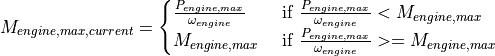
When 98% of the maximum speed of the motor is reached (“MaximumEngineSpeed” in the VehicleCatalog), the engine torque is linearly reduced to 0.
The maximum engine torque is scaled via the accelerator pedal position (input). This value is calculated back to the total wheel drive torque via the gear ratio.

The wheel total drive torque is evenly distributed to the wheels of an axle according to the definition of the drive type. With all-wheel drive, the entire wheel drive torque is distributed statically over the defined ratio.
ActionBrakeSystem
The brake model is a linearized model. The brake pedal position is used as input. As output, the model returns the braking torques of the wheels as a vector. The model considers a response time [ms] and linear factors [m/s³] for the increase and decrease of the braking force.The distribution of braking force between the front and rear axles can be defined statically.
Attribute |
Type |
Unit |
Description |
|---|---|---|---|
FrontAxlePercentage |
Double |
Distribution of the brake torque to the front axle in the case of all-wheel drive (AWD); Range 0-1 |
|
BrakeDecelerationInclineRate |
Double |
m/s³ |
Linear Rate of braking force increase |
BrakeDecelerationDeclineRate |
Double |
m/s³ |
Linear Rate of braking force decrease |
BrakeResponseTimeMs |
Double |
ms |
Brake response time |
The maximum braking force of the system is determined from the maximum possible deceleration and the mass of the vehicle and is scaled by the brake pedal position (Input). The maximum possible deceleration and the vehicle mass are obtained from the VehicleCatalog (“maxDeceleration” & “mass”).

When the brake is applied, a deceleration is calculated after the response time has elapsed. Then the braking force is built up linearly until the maximum or requested braking force has been reached.

When the brake is released, the braking force is dissipated with the decline rate until it has dropped to zero. After that, the response time builds up again. The braking force is divided among the axles according to the parameter “FrontAxlePercentage”. Another input allows you to request a prefill that reduces the response time without braking
DynamicsChassis
The chassis model determines the vertical forces of the four wheels from the longitudinal and lateral acceleration of the vehicle. Constant spring and damper rates are taken into account, which can be defined by the following parameters per axis:
Attribute |
Type |
Unit |
Description |
|---|---|---|---|
SpringCoefficient |
VectorDouble |
N/m |
Constant spring coefficient for each axis |
DamperCoefficient |
VectorDouble |
Ns/m |
Constant damper coefficient for each axis |
DynamicsTireModel
The tire model is freely configurable and includes a degressive behaviour. The tire forces are modeled according to Rill using the TMEasy model. The following parameters can be set for the tire model per axis :
Attribute |
Type |
Unit |
Description |
|---|---|---|---|
MuTireMaxXFRef |
VectorDouble |
Normalized scaling factor for maximum longitudinal force at reference vertical force |
|
MuTireMaxX2FRef |
VectorDouble |
Normalized scaling factor for maximum longitudinal force at double reference vertical force |
|
MuTireSlideXFRef |
VectorDouble |
Normalized scaling factor for sliding longitudinal force at reference vertical force |
|
MuTireSlideX2FRef |
VectorDouble |
Normalized scaling factor for sliding longitudinal force at double reference vertical force |
|
SlipTireMaxXFRef |
VectorDouble |
Longitudinal slip at maximum longitudinal force at reference vertical force |
|
SlipTireMaxX2FRef |
VectorDouble |
Longitudinal slip at maximum longitudinal force at double reference vertical force |
|
SlipTireSlideXFRef |
VectorDouble |
Longitudinal slip at sliding longitudinal force at reference vertical force |
|
SlipTireSlideX2FRef |
VectorDouble |
Longitudinal slip at sliding longitudinal force at double reference vertical force |
|
F0pXFRef |
VectorDouble |
N |
Initial slope of longitudinal force at reference force |
F0pX2FRef |
VectorDouble |
N |
Initial slope of longitudinal force at double reference force |
MuTireMaxYFRef |
VectorDouble |
Normalized scaling factor for maximum lateral force at reference vertical force |
|
MuTireMaxY2FRef |
VectorDouble |
Normalized scaling factor for maximum lateral force at double reference vertical force |
|
MuTireSlideYFRef |
VectorDouble |
Normalized scaling factor for sliding lateral force at reference vertical force |
|
MuTireSlideY2FRef |
VectorDouble |
Normalized scaling factor for sliding lateral force at double reference vertical force |
|
SlipTireMaxYFRef |
VectorDouble |
Lateral slip at maximum lateral force at reference vertical force |
|
SlipTireMaxY2FRef |
VectorDouble |
Lateral slip at maximum lateral force at double reference vertical force |
|
SlipTireSlideYFRef |
VectorDouble |
Lateral slip at sliding lateral force at reference vertical force |
|
SlipTireSlideY2FRef |
VectorDouble |
Lateral slip at sliding lateral force at double reference vertical force |
|
F0pYFRef |
VectorDouble |
N |
Initial slope of lateral force at reference force |
F0pY2FRef |
VectorDouble |
N |
Initial slope of lateral force at double reference force |
FRef |
VectorDouble |
N |
Vertical reference force for the tire parameters |
FRefNormalized |
VectorBool |
Should the reference force be scaled with the static vertical tire force? |
|
Inertia |
VectorDouble |
kgm² |
Inertia of tire |
PneumaticTrail |
VectorDouble |
m |
Pneumatic trail of tire |
The normalized factors refer to the reference vertical force or to the double reference vertical force The input variables used by the model are tire drive and braking torques as well as the wheel angles and vertical wheel forces. All data is provided as vectors. The model determines tire forces in the longitudinal and lateral directions as well as the wheel self aligning torques. The wheel self aligning torque is formed from the product of the tire side force and the pneumatic trail. A linear interpolation is performed between the values for the reference force and the double reference force. If no degressive tire behavior is desired, the parameters for the double reference force must be set identically to the values for the reference force.
All forces are scaled with the coefficient of friction from the VehicleCatalog (“FrictionCoefficient”).
All further information about the model can be found in the following sources:
Rill, Georg. (2013). TMeasy – A Handling Tire Model based on a three-dimensional slip approach.
DynamicsMotionModel
The motion model converts the tire forces (input) into a translational and rotational movement of the vehicle. The air resistance of the vehicle is taken into account. For the dynamic calculation, the center of gravity position is taken from the VehicleCatalog (“XPositionCOG”,”YPositionCOG”), which indicates the distance of the center of gravity to the center of the rear axle. If this data is not given, the center of gravity is positioned on half wheelbase. For air resistance, the properties “AirDragCoefficient” & “FrontSurface” from the VehicleCatalog are used.
For the equations of motion, see relevant vehicle dynamics books such as:
Kücükay, Ferit (2022), “Grundlagen der Fahrzeugtechnik”, page 1067 ff