World_OSI
Sampling of World Geometries
Roads are described following the OpenDRIVE specification. There the geometry of a road is defined algebraically as lines, clothoids and by means of cubic polynomials, whereby primarily only one reference line is defined. The lanes can be understood as a stack of parallel lanes, which are given by the width and the offset, now in relation to this reference line, which acts as the underlying coordinate system (‘s/t’ road coordinates with s along the road). Here, too, width and offset are defined algebraically, which means that almost any boundary lines can be defined.
When the world is initialized, these boundary definitions (i.e. algebraic geometries) are converted into piecewise linear elements, which is called sampling. The road is scanned at a constant interval along ‘s’, which leads to four-sided (quadrangular) sections of the lanes at common ‘s’ coordinates, so-called lane elements (see LaneElement). The scanning is carried out at a scanning rate of 10 centimeters with the aim of achieving a total scanning error of less than 5 centimeters, as required by the representation used internally (c.f. open simulation interface). Note that this error is only guaranteed if geometries do not exhibit extreme curvatures, i.e. a deviation of more than 5 cm within two sampling points (10 cm along s). The scanned points define so-called joints, which contain all scanned points at an ‘s’ coordinate across all lane boundaries of the given road. The number of these joints is reduced by a Ramer-Douglas-Peucker algorithm, which ensures that the maximum lateral error of each individual point within a joint is less than 5 cm compared to the originally scanned points. Note that (a) the boundary points of geometries are always retained and (b) additional points for lane marking transitions are also retained to ensure the maximum accuracy of these edge cases. The lane elements are generated with two successive connections, which are ultimately used in the localization at runtime (see Localization).
Internally, each lane element receives a constant direction, which is defined by the direction of the vector spanned between the centers of the corresponding connections. Each joint also holds the corresponding curvature of the road, so that the curvature can be interpolated linearly within a lane element along the ‘s’ coordinate.
Localization
Generally, the position of an agent is stored with respect to world coordinates (x,y). As queries on the world operates in road coordinates (s,t), the position of the agent needs to be transformed.
This section describes the translation of coordinates (x,y) of an agent into RoadCoordinate (s,t), whereas the notion of (s,t) comes from the OpenDRIVE standard.
Basics
The following image depics the basic principes of the localization which is rooted on the specifics of the OSI World Layer (aka OWL).

Localization Basics
Given is a point P in cartesian coordinates (x/y). The task is to assign the point to a lane, defined by a general road geometry and calculate the transformed Point P’ in road coordinates (s/t).
Road geometry (based on OpenDRIVE):
A road consists of several sections
Each section consists of several lanes
Within a section, the number of lanes is constant
Lanes can have one predecessor and one successor
The road follows a reference line, which is the reference for the s-coordinate. The t-coordinate is perpendicular to this line.
OWL specifics:
All lanes are sampled, generating a stream of generic quadrilaterals (LaneGeometryElements).
Within a section, the number of quads per lane is equal, and all lanes have the same length in s.
This is realized by a variable sampling width, determined by a constant sampling width along the longest arc.
Consequently, points perpendicular to the reference line (t-axis) have the same s-coordinate.
Note, that the final t-coordinate is calculated with respect to a virtual reference line for each lane. This means, that points on the center of a lane have t-coordinate of 0.
Localization sequence
An r-tree is used to store each LaneGeometryElement. Thereby, due to the nature of the r-tree, the bounding box of the LaneGeometryElement is described by its maximum Cartesian coordinates (x_min, x_max, y_min, y_max). Objects are located by retrieving all intersecting bounding boxes from the r-tree. The picture below shows an example of an agent (blue) with the corresponding Cartesian bounding box, and all located LaneGeometryElements.
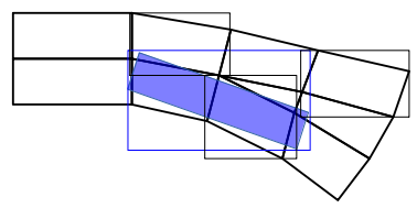
Example of bounding boxes of LaneGeometryElements and agent
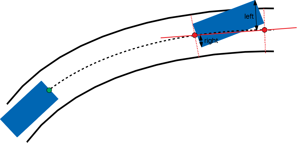
As the true boundary polygon may be smaller, the actual intersection polygon of the object and each LaneGeometryElement is calculated. For each point of a non-empty intersection polygon, the s and t coordinates are calculated and aggregated with respect to the underlying lane. For each touched lane, the minimum and maximum s coordinate, and the minimum and maximum lane remainder (delta t) is stored.

Example for the calculation of s_min, s_max and delta_left
In addition, if the reference point (i.e. the middle of the rear axle) or the mainLaneLocator (i.e. the middle of the agent front) are located within a LaneGeometryElement, s/t/yaw is calculated of each point, respectively. Further aggregation is done with respect to each road by calculating the minimum and maximum s for each road the agent intersects with. For the current route of an agent, the following information is stored: s/t/yaw of the reference point and mainLaneLocator on the route (roads along a route are not allowed to intersect), distance from the lane boundary to the left and right for the road(s) along the route, and OpenDRIVE Ids of the lanes on the route that the agent touches. The results also holds information whether both the reference point and the mainLaneLocator lay on the route. In the current implementation, these points must be located - otherwise the agent is despawened, as the agent cannot execute distance queries without a relation to its current route.
Traffic Signs, Road Markings and TrafficLights
The world currently supports a variety of traffic signs, road markings and traffic lights. All of these are defined in OpenDRIVE as “RoadSignal”. At the moment it can interpret traffic signs and road markings according to the German regulations, US regulations, and China regulations and traffic lights according the the OpenDRIVE appendix. Traffic signs can contain optional supplementary traffic signs. Supplementary signs are dependent on a main traffic sign and contain additional information.
For Germany the types are based on the StVO (see: https://www.bast.de/BASt_2017/DE/Verkehrstechnik/Fachthemen/v1-verkehrszeichen/vz-download.html). The following traffic signs are supported for Germany:
TrafficSign |
Image |
StVo Type |
Subtype |
Value and Units |
|---|---|---|---|---|
GiveWay |

|
205 |
||
Stop |

|
206 |
||
DoNotEnter |

|
267 |
||
EnvironmentalZoneBegin |

|
270.1 |
||
EnvironmentalZoneEnd |

|
270.2 |
||
MaximumSpeedLimit |


|
274 |
X |
The subtype “X” is used to define the speedlimit in km/h. Afterwards the world converts it to m/s. |
SpeedLimitZoneBegin |


|
274.1 |
-/20 |
The subtype is used to define the speedlimit in km/h. Afterwards the world converts it to m/s. No subtype = 30km/h, 20 = 20km/h |
SpeedLimitZoneEnd |


|
274.2 |
-/20 |
The subtype is used to define the speedlimit in km/h. Afterwards the world converts it to m/s. No subtype = 30km/h, 20 = 20km/h |
MinimumSpeedLimit |

|
275 |
X |
The subtype is used to define the speedlimit in km/h. Afterwards the world converts it to m/s. |
OvertakingBanBegin |

|
276 |
||
OvertakingBanTrucksBegin |

|
277 |
||
EndOfMaximumSpeedLimit |


|
278 |
X |
The subtype “X” is used to define the speedlimit in km/h. Afterwards the world converts it to m/s. |
EndOfMinimumSpeedLimit |

|
279 |
X |
The subtype “X” is used to define the speedlimit in km/h. Afterwards the world converts it to m/s. |
OvertakingBanEnd |

|
280 |
||
OvertakingBanTrucksEnd |

|
281 |
||
EndOffAllSpeedLimitsAndOvertakingRestrictions |

|
282 |
||
RightOfWayNextIntersection |

|
301 |
||
RightOfWayBegin |

|
306 |
||
RightOfWayEnd |

|
307 |
||
TownBegin |

|
310 |
This sign contains a text describing the name of the town |
|
TownEnd |

|
311 |
This sign contains a text describing the name of the town |
|
TrafficCalmedDistrictBegin |

|
325.1 |
||
TrafficCalmedDistrictEnd |

|
325.2 |
||
HighWayBegin |

|
330.1 |
||
HighWayEnd |

|
330.2 |
||
HighWayExit |

|
333 |
||
AnnounceHighwayExit |

|
448 |
||
PreannounceHighwayExitDirections |

|
449 |
||
HighwayExitPole |


|
450 |
50/51/52 |
The subtype describes the distance to the highway exit in m. 50 = 100m, 51 = 200m, 52 = 300m |
AnnounceRightLaneEnd |


|
531 |
10/11/12/13 |
The subtype describes the number of continuing lanes after the right lane ends. 10 = 1 lane, 11 = 2 lanes, 12 = 3 lanes, 13 = 4 lanes |
AnnounceLeftLaneEnd |


|
531 |
20/21/22/23 |
The subtype describes the number of continuing lanes after the left lane ends. 10 = 1 lane, 11 = 2 lanes, 12 = 3 lanes, 13 = 4 lanes |
DistanceIndication |


|
1004 |
30/31/32 |
For subtype 30 the value describes the distance in m. For subtype 31 the value describes the distance in km. Subtype 32 has a STOP in 100m. |
The following road markings are supported for Germany:
RoadMarking |
Image |
StVo Type |
Subtype |
Value and Units |
|---|---|---|---|---|
PedestrianCrossing |

|
293 |
||
Stop line |

|
294 |
The pedestrian crossing can also be defined in OpenDRIVE as object with type “crosswalk”.
For United States the types are based on the “Manual on Uniform Traffic Control Devices” (see: https://mutcd.fhwa.dot.gov/pdfs/2009r1r2/pdf_index.htm). The following traffic signs are supported for United States:
TrafficSign |
Image |
Type |
Value and Units |
|---|---|---|---|
HighWayExit |

|
E5-1 |
|
HighWayExit |

|
E2-5 |
|
AnnounceHighwayExit |

|
E1-2 |
|
PreannounceHighwayExit |

|
E1-2a |
|
Stop |

|
R1-1 |
|
GiveWay |

|
R1-2 |
|
MaximumSpeedLimit |

|
R2-1 |
as defined via the “value” and “unit” attributes |
DoNotPass (OvertakingBan) |

|
R4-1 |
|
DoNotEnter |

|
R5-1 |
|
RightLaneEnd |

|
W4-2R |
|
LeftLaneEnd |

|
W4-2L |
For China the types are based on the https://upload.wikimedia.org/wikipedia/commons/8/8c/China_GB_5768.2-2009.pdf. The following traffic signs are supported for China:
TrafficSign |
Image |
Type |
Subtype |
Value and Units |
|---|---|---|---|---|
AnnounceRightLaneEnd |


|
EndofLane-32 |
a/b |
The subtype describes the number of continuing lanes after the right lane ends. a = 2 lanes, b = 3 lanes |
AnnounceLeftLaneEnd |


|
EndofLane-32 |
c/d |
The subtype describes the number of continuing lanes after the left lane ends. c = 2 lanes, d = 3 lanes |
MaximumSpeedLimit |

|
SpeedLimit-38 |
as defined via the “value” and “unit” attributes |
|
EndOfMaximumSpeedLimit |

|
EndOfSpeedLimit-39 |
as defined via the “value” and “unit” attributes |
|
AnnounceHighwayExit (1km) |

|
AnnounceHighwayExit-50b |
||
AnnounceHighwayExit (500m) |

|
AnnounceHighwayExit-50c |
||
HighWayExit |

|
HighwayExit-50d |
The following traffic lights are supported:
TrafficLight |
OpenDRIVE Type |
Subtype |
Value and Units |
|---|---|---|---|
Standard traffic light (red, yellow, green) |
1.000.001 |
- |
- |
Left arrows |
1.000.011 |
10 |
- |
Right arrows |
1.000.011 |
20 |
- |
Upwards arrows |
1.000.011 |
30 |
- |
Left und upwards arrows |
1.000.011 |
40 |
- |
Right und upwards arrows |
1.000.011 |
50 |
- |
These traffic lights are controlled by OpenScenario.
Lane Markings
The world also supports lane markings (i.e. printed lines between two lanes) according to the OpenDRIVE standard. The following attributes of the “roadMark” tag in the scenery file are stored in the world and can be retrieved by the GetLaneMarkings query: sOffset, type, weight, color. The weight is converted into a width in meter: 0.15 for standard and 0.3 for bold. Lane markings are also converted to OSI LaneBoundaries. For the OpenDRIVE type “solid solid”, “solid broken”, “broken solid”, and “broken broken” two LaneBoundaries are created in OSI with a fixed lateral distance of 0.15m.
GetObstruction
The GetObstruction function calculates the lateral distance an agent must travel in order to align with either the left or right boundary of a target object occupying the same lane.
The calculation adheres to the following process:
Project the agent’s MainLaneLocator along the lane to the nearest and furthest s-coordinate of the target object, capturing the projected points
Create a straight line from the two captured points
Calculate the Euclidean distance of each of the target object’s corners to the created line
Return the left-most and right-most points with respect to the created line
If the first step fails, because the ego lane does not extend to the object’s position (i. e. it ends prematurely or the objects is outside the ego’s route), then the result is invalid, which is indicated by a separate valid flag.
Example for the calculation of GetObstruction