Home » Eclipse Projects » GEF » [GEF4] Calculation of stroke outline in model
| [GEF4] Calculation of stroke outline in model [message #1734940] |
Mon, 13 June 2016 23:44  |
|
I have parts that render a PolyBezier using a stroke width that is specified by the model object. The model object is just storing the PolyBezier (which is infinitely thin) and an int for the stroke width. However, I'd like to be able to calculate the actual outline of the rendered geometry in the model code as well.
It's clear that something in either GEF4 or JavaFX is able to do this, as I can see that hit detection is using the outline of the stroke rather than just the actual model PolyBezier - I just can't see where this happens in the code.
The reason I need this is that I might have two shapes with different stroke widths that connect up, and rather than having an abrupt change from one stroke width to the other, I want to create a new connection object that has an outline that smoothly increases the stroke. To do that, I'd need to be able to identify points on the outer edges of the strokes, so that I can then create a polygon to join them together.
I'll try some ASCII art to illustrate. Imagine that each character is a pixel. The 'x' marks a waypoint on the model object. There are two lines, which share a common point at the third x. The first line has a stroke width of 3, so the 'a's represent the pixels filled by that line; the second line has a stroke width of 9, represented by the 'c's.
                           4ccccccccccccccccccccccccccccccc
                           cccccccccccccccccccccccccccccccc
                           cccccccccccccccccccccccccccccccc
aaaaaaaaaaaa1aaaaaaaaaaaaaacccccccccccccccccccccccccccccccc
xaaaaaaaaaaaxaaaaaaaaaaaaaxcccccccccccccccccxcccccccccccccx
aaaaaaaaaaaa2aaaaaaaaaaaaaacccccccccccccccccccccccccccccccc
                           cccccccccccccccccccccccccccccccc
                           cccccccccccccccccccccccccccccccc
                           3ccccccccccccccccccccccccccccccc
The points I want to identify are represented by numbers 1, 2, 3 and 4 - I would use these to create a polygon which would be rendered underneath the other two, represented by the 'o's here:
                           4ccccccccccccccccccccccccccccccc
                     oooooocccccccccccccccccccccccccccccccc
               oooooooooooocccccccccccccccccccccccccccccccc
aaaaaaaaaaaa1aaaaaaaaaaaaaacccccccccccccccccccccccccccccccc
xaaaaaaaaaaaxaaaaaaaaaaaaaxcccccccccccccccccxcccccccccccccx
aaaaaaaaaaaa2aaaaaaaaaaaaaacccccccccccccccccccccccccccccccc
                ooooooooooocccccccccccccccccccccccccccccccc
                    ooooooocccccccccccccccccccccccccccccccc
                           3ccccccccccccccccccccccccccccccc
I have come up with a couple of algorithms to generate these points, based on making a polyline approximation of the PolyBezier, then creating a series of polygons of the appropriate width using the straight lines as the centre. (Note, the version using Ring to join the polygons together produces a more accurate outline but has terrible performance).
However, it strikes me that something must already be doing this for hit detection to work. If it's happening in the JavaFX layer, then I probably can't use it in the model code, but if it's in the GEF4 layer then I should be able to use it. Where should I be looking?
Colin Sharples
CTG Games Ltd
Wellington, New Zealand
|
|
|
| Re: [GEF4] Calculation of stroke outline in model [message #1734947 is a reply to message #1734940] |
Tue, 14 June 2016 04:48  |
|
Hi Colin,
within GEF4 there is currently no functionality that allows to calculate such a "fat-line" for a PolyBezier. We have raised https://bugs.eclipse.org/bugs/show_bug.cgi?id=495290 in order to add such a functionality to NodeUtils#getShapeOutline(Node).
The related computations within JavaFX are internal and AFAIK there is no public API to access it. That's the reason why the shape outline we compute for shape geometries within NodeUtils#getShapeOutline(Node) is only an approximation as well (it simply resizes the geometry to the shape/layout bounds that contain the stroke; this is not precise, as it does not consider the 'effect' of line cap and join properly). As such, computing an approximation as you do is probably the best that can be done.
Regards,
Alexander
PS: Can you please raise an issue concerning the poor performance of the Ring geometry (providing a snippet or some data that allows us to investigate this in more detail)?
[Updated on: Tue, 14 June 2016 04:50] Report message to a moderator |
|
| |
| Re: [GEF4] Calculation of stroke outline in model [message #1735200 is a reply to message #1735148] |
Thu, 16 June 2016 10:00 |
|
Hi Colin,
while it is true that curve offsetting is not supported by the Geometry component, yet, and the JavaFX functionality is indeed internal, the points that are needed can be computed using the Geometry component as follows:
1) Find the BezierCurve within the PolyBezier that contains the two "x" points before/at the joint of the two curves. This should either be the last or the second to last BezierCurve within the array returned by PolyBezier#toBezier().
2) Compute the first derivative of that BezierCurve in order to offset the point by the stroke width. The first derivative of a BezierCurve is called its hodograph and be accessed using BezierCurve#getDerivative().
3) Offset the "x" points by the stroke width. Suppose the first "x" point is called startPoint, and the last "x" point (i.e. the one at the joint) is called endPoint. The startPoint needs to be offset by the start curve's stroke width, the endPoint needs to be offset twice: once for the start curve's stroke width, and once for the end curve's stroke width.
The following snippet demonstrates the computation:
import org.eclipse.gef4.fx.utils.Geometry2Shape;
import org.eclipse.gef4.geometry.euclidean.Vector;
import org.eclipse.gef4.geometry.planar.BezierCurve;
import org.eclipse.gef4.geometry.planar.Line;
import org.eclipse.gef4.geometry.planar.Point;

import javafx.application.Application;
import javafx.scene.Scene;
import javafx.scene.layout.Pane;
import javafx.scene.paint.Color;
import javafx.scene.shape.Path;
import javafx.scene.shape.Polygon;
import javafx.scene.shape.StrokeLineCap;
import javafx.scene.shape.StrokeLineJoin;
import javafx.scene.shape.StrokeType;
import javafx.stage.Stage;

public class CurveOffsetSnippet extends Application {

	public static void main(String[] args) {
		launch();
	}

	protected void addCurves(Pane root, double y, boolean transition) {
		// create curves
		BezierCurve firstCurve = new Line(100, y, 200, y);
		BezierCurve secondCurve = new Line(200, y, 300, y);

		// create paths
		Path firstPath = Geometry2Shape.toPath(firstCurve.toPath());
		Path secondPath = Geometry2Shape.toPath(secondCurve.toPath());

		// add to scene
		root.getChildren().addAll(firstPath, secondPath);

		// strokes
		double firstStrokeWidth = 5;
		double secondStrokeWidth = 15;

		// configure strokes
		firstPath.setStrokeType(StrokeType.CENTERED);
		firstPath.setStrokeWidth(firstStrokeWidth);
		firstPath.setStrokeLineCap(StrokeLineCap.BUTT);
		firstPath.setStrokeLineJoin(StrokeLineJoin.BEVEL);
		firstPath.setStroke(Color.DARKRED);

		secondPath.setStrokeType(StrokeType.CENTERED);
		secondPath.setStrokeWidth(secondStrokeWidth);
		secondPath.setStrokeLineCap(StrokeLineCap.BUTT);
		secondPath.setStrokeLineJoin(StrokeLineJoin.BEVEL);
		secondPath.setStroke(Color.DARKRED);

		// compute polygons to transition from the thinner/first curve to
		// the thicker/second curve
		if (transition) {
			// compute start point and end point
			Point startPoint = firstCurve.get(0);
			Point endPoint = firstCurve.get(1);

			// compute curve normals for start point and end point
			Vector startNormal = new Vector(firstCurve.getDerivative().get(0))
					.getOrthogonalComplement().getNormalized();
			Vector endNormal = new Vector(firstCurve.getDerivative().get(1))
					.getOrthogonalComplement().getNormalized();

			// compute left and right offset points for the start point (first
			// curve stroke width)
			Point startOffsetLeft = startPoint.getTranslated(
					startNormal.getMultiplied(firstStrokeWidth / 2).toPoint());
			Point startOffsetRight = startPoint.getTranslated(
					startNormal.getMultiplied(firstStrokeWidth / 2).toPoint()
							.getNegated());

			// compute left and right offset points for the end point (first
			// curve stroke width)
			Point endThinOffsetLeft = endPoint.getTranslated(
					endNormal.getMultiplied(firstStrokeWidth / 2).toPoint());
			Point endThinOffsetRight = endPoint
					.getTranslated(endNormal.getMultiplied(firstStrokeWidth / 2)
							.toPoint().getNegated());

			// compute left and right offset points for the end point (second
			// curve stroke width)
			Point endOffsetLeft = endPoint.getTranslated(
					endNormal.getMultiplied(secondStrokeWidth / 2).toPoint());
			Point endOffsetRight = endPoint.getTranslated(
					endNormal.getMultiplied(secondStrokeWidth / 2).toPoint()
							.getNegated());

			// compute left and right polygons for a smooth transition between
			// the stroke widths
			Polygon leftPolygon = new Polygon(startOffsetLeft.x,
					startOffsetLeft.y, endThinOffsetLeft.x, endThinOffsetLeft.y,
					endOffsetLeft.x, endOffsetLeft.y);
			Polygon rightPolygon = new Polygon(startOffsetRight.x,
					startOffsetRight.y, endThinOffsetRight.x,
					endThinOffsetRight.y, endOffsetRight.x, endOffsetRight.y);

			// fill with stroke color
			leftPolygon.setFill(Color.DARKRED);
			rightPolygon.setFill(Color.DARKRED);

			// add to scene
			root.getChildren().addAll(leftPolygon, rightPolygon);
		}
	}

	@Override
	public void start(Stage primaryStage) throws Exception {
		Pane root = new Pane();
		Scene scene = new Scene(root, 400, 400);

		addCurves(root, 100.5, false);
		addCurves(root, 200.5, true);

		primaryStage.setScene(scene);
		primaryStage.show();
	}

}
|
|
|
| Re: [GEF4] Calculation of stroke outline in model [message #1735279 is a reply to message #1735200] |
Thu, 16 June 2016 22:02 |
|
Ah, so that's what a hodograph is used for, I wondered about that 
Thanks Matthias, that's really cool. Actually, the shapes I'm joining together are constructed from QuadraticCurves rather than lines, so I have modified your example to create a PolyBezier from two new curves using the calculated offsets - I also offset the curve's control point in a similar manner to the start and end offsets. That produces a really beautiful effect, just what I was looking for. GEF4 rocks!
package nz.co.ctg.mote.client.test;

import org.eclipse.gef4.fx.nodes.GeometryNode;
import org.eclipse.gef4.fx.utils.Geometry2Shape;
import org.eclipse.gef4.geometry.euclidean.Vector;
import org.eclipse.gef4.geometry.planar.BezierCurve;
import org.eclipse.gef4.geometry.planar.Line;
import org.eclipse.gef4.geometry.planar.Point;
import org.eclipse.gef4.geometry.planar.PolyBezier;
import org.eclipse.gef4.geometry.planar.QuadraticCurve;

import javafx.application.Application;
import javafx.scene.Scene;
import javafx.scene.layout.Pane;
import javafx.scene.paint.Color;
import javafx.scene.shape.Path;
import javafx.scene.shape.StrokeLineCap;
import javafx.scene.shape.StrokeLineJoin;
import javafx.scene.shape.StrokeType;
import javafx.stage.Stage;

public class QuadCurveOffsetSnippet extends Application {

  public static void main(String[] args) {
    launch();
  }

  protected void addCurves(Pane root, double y, boolean transition) {
    // create curves
    QuadraticCurve firstCurve = new QuadraticCurve(100, y, 150, y - 50, 200, y);
    BezierCurve secondCurve = new QuadraticCurve(200, y, 250, y + 50, 300, y);

    // create paths
    Path firstPath = Geometry2Shape.toPath(firstCurve.toPath());
    Path secondPath = Geometry2Shape.toPath(secondCurve.toPath());


    // strokes
    double firstStrokeWidth = 16;
    double secondStrokeWidth = 48;

    // configure strokes
    firstPath.setStrokeType(StrokeType.CENTERED);
    firstPath.setStrokeWidth(firstStrokeWidth);
    firstPath.setStrokeLineCap(StrokeLineCap.BUTT);
    firstPath.setStrokeLineJoin(StrokeLineJoin.BEVEL);
    firstPath.setStroke(Color.BLUE);

    secondPath.setStrokeType(StrokeType.CENTERED);
    secondPath.setStrokeWidth(secondStrokeWidth);
    secondPath.setStrokeLineCap(StrokeLineCap.BUTT);
    secondPath.setStrokeLineJoin(StrokeLineJoin.BEVEL);
    secondPath.setStroke(Color.BLUE);

    // compute polygons to transition from the thinner/first curve to
    // the thicker/second curve
    if (transition) {
      // compute start point and end point
      Point startPoint = firstCurve.get(0);
      Point endPoint = firstCurve.get(1);
      Point controlPoint = firstCurve.getCtrl();

      // compute curve normals for start point and end point
      Vector startNormal = new Vector(firstCurve.getDerivative().get(0)).getOrthogonalComplement().getNormalized();
      Vector endNormal = new Vector(firstCurve.getDerivative().get(1)).getOrthogonalComplement().getNormalized();

      // compute left and right offset points for the start point (first
      // curve stroke width)
      Point startOffsetLeft = startPoint.getTranslated(startNormal.getMultiplied(firstStrokeWidth / 2).toPoint());
      Point startOffsetRight = startPoint.getTranslated(startNormal.getMultiplied(firstStrokeWidth / 2).toPoint().getNegated());

      // compute left and right offset points for the quadratic curve control point
      Point ctrlOffsetLeft = controlPoint.getTranslated(startNormal.getMultiplied(firstStrokeWidth / 2).toPoint());
      Point ctrlOffsetRight = controlPoint.getTranslated(startNormal.getMultiplied(firstStrokeWidth / 2).toPoint().getNegated());

      // compute left and right offset points for the end point (second
      // curve stroke width)
      Point endOffsetLeft = endPoint.getTranslated(endNormal.getMultiplied(secondStrokeWidth / 2).toPoint());
      Point endOffsetRight = endPoint.getTranslated(endNormal.getMultiplied(secondStrokeWidth / 2).toPoint().getNegated());

      // compute left and right curves for a smooth transition between
      // the stroke widths
      BezierCurve left = new QuadraticCurve(startOffsetLeft, ctrlOffsetLeft, endOffsetLeft);
      BezierCurve cap = new Line(endOffsetLeft, endOffsetRight);
      BezierCurve right = new QuadraticCurve(endOffsetRight, ctrlOffsetRight, startOffsetRight);
      PolyBezier cone = new PolyBezier(left, cap, right);

      // add to scene
      GeometryNode<PolyBezier> coneNode = new GeometryNode<PolyBezier>(cone);
      coneNode.setFill(Color.BLUE);
      coneNode.setStroke(Color.BLUE);
      coneNode.setStrokeLineCap(StrokeLineCap.BUTT);
      coneNode.setStrokeLineJoin(StrokeLineJoin.BEVEL);

      root.getChildren().add(coneNode);
    }
    // add to scene
    root.getChildren().addAll(firstPath, secondPath);
  }

  @Override
  public void start(Stage primaryStage) throws Exception {
    Pane root = new Pane();
    Scene scene = new Scene(root, 400, 400);

    addCurves(root, 100.5, false);
    addCurves(root, 200.5, true);

    primaryStage.setScene(scene);
    primaryStage.show();
  }

}
Colin Sharples
CTG Games Ltd
Wellington, New Zealand
|
|
|
| Re: [GEF4] Calculation of stroke outline in model [message #1735282 is a reply to message #1735279] |
Thu, 16 June 2016 22:55 |
|
Oops, just realized that the control point offset would be more accurate if it was using the derivative at the point of the curve closest to where the control point is, so when calculating the control offsets I changed it to:
      Point ctrlOffset = firstCurve.getProjection(firstCurve.getCtrl());
      Vector ctrlNormal = new Vector(firstCurve.getDerivative().get(firstCurve.getParameterAt(ctrlOffset))).getOrthogonalComplement().getNormalized();
      Point ctrlOffsetLeft = controlPoint.getTranslated(ctrlNormal.getMultiplied(firstStrokeWidth / 2).toPoint());
      Point ctrlOffsetRight = controlPoint.getTranslated(ctrlNormal.getMultiplied(firstStrokeWidth / 2).toPoint().getNegated());
Even that is not absolutely accurate - the amount by which the control point should be offset is proportional to how bendy that curve is, but my maths isn't good enough to figure out what that relationship is - but it's definitely something to do with the distance between the control point and the projection of the control point on the curve.
Colin Sharples
CTG Games Ltd
Wellington, New Zealand
|
|
|
| Re: [GEF4] Calculation of stroke outline in model [message #1735302 is a reply to message #1735282] |
Fri, 17 June 2016 08:32 |
|
Hey that looks cool indeed!
I manipulated the code further to accurately align the shapes:
- Compute control points for cones so that C1 continuity is achieved.
- Set stroke to transparent for the cones to properly align the shapes.
		if (transition) {
			// compute start point and end point of the transition curve
			Point startPoint = firstCurve.get(0);
			Point endPoint = firstCurve.get(1);

			// compute derivatives for start/end
			BezierCurve derivative = firstCurve.getDerivative();
			Vector startDirection = new Vector(derivative.get(0));
			Vector endDirection = new Vector(derivative.get(1));

			// compute curve normals for start point and end point
			Vector startNormal = startDirection.getOrthogonalComplement()
					.getNormalized();
			Vector endNormal = endDirection.getOrthogonalComplement()
					.getNormalized();

			// compute left and right offset points for the start point (first
			// curve stroke width)
			Point startOffsetLeft = startPoint.getTranslated(
					startNormal.getMultiplied(firstStrokeWidth / 2).toPoint());
			Point startOffsetRight = startPoint.getTranslated(
					startNormal.getMultiplied(firstStrokeWidth / 2).toPoint()
							.getNegated());

			// compute left and right offset points for the end point (second
			// curve stroke width)
			Point endOffsetLeft = endPoint.getTranslated(
					endNormal.getMultiplied(secondStrokeWidth / 2).toPoint());
			Point endOffsetRight = endPoint.getTranslated(
					endNormal.getMultiplied(secondStrokeWidth / 2).toPoint()
							.getNegated());

			// compute control points by intersecting the derivatives through
			// the offsetted start/end points to achieve C1 continuity
			Straight s1Left = new Straight(new Vector(startOffsetLeft),
					startDirection);
			Straight s2Left = new Straight(new Vector(endOffsetLeft),
					endDirection);
			Vector ctrlOffsetLeft = s1Left.getIntersection(s2Left);
			if (ctrlOffsetLeft == null) {
				ctrlOffsetLeft = new Vector(endOffsetLeft);
			}

			Straight s1Right = new Straight(new Vector(startOffsetRight),
					startDirection);
			Straight s2Right = new Straight(new Vector(endOffsetRight),
					endDirection);
			Vector ctrlOffsetRight = s1Right.getIntersection(s2Right);
			if (ctrlOffsetRight == null) {
				ctrlOffsetRight = new Vector(endOffsetRight);
			}

			// compute left and right curves for a smooth transition between
			// the stroke widths
			org.eclipse.gef4.geometry.planar.Path leftCone = new org.eclipse.gef4.geometry.planar.Path(
					new Segment(Segment.MOVE_TO, startOffsetLeft),
					new Segment(Segment.QUAD_TO, ctrlOffsetLeft.toPoint(),
							endOffsetLeft),
					new Segment(Segment.LINE_TO, endPoint),
					new Segment(Segment.QUAD_TO, firstCurve.getCtrl(),
							startPoint),
					new Segment(Segment.CLOSE));
			org.eclipse.gef4.geometry.planar.Path rightCone = new org.eclipse.gef4.geometry.planar.Path(
					new Segment(Segment.MOVE_TO, endOffsetRight),
					new Segment(Segment.QUAD_TO, ctrlOffsetRight.toPoint(),
							startOffsetRight),
					new Segment(Segment.LINE_TO, startPoint),
					new Segment(Segment.QUAD_TO, firstCurve.getCtrl(),
							endPoint),
					new Segment(Segment.CLOSE));
			Line capLine = new Line(endOffsetLeft, endOffsetRight);

			// create corresponding JavaFX shapes
			Path leftConeShape = Geometry2Shape.toPath(leftCone);
			Path capShape = Geometry2Shape.toPath(capLine.toPath());
			Path rightConeShape = Geometry2Shape.toPath(rightCone);

			// style the shapes for accurate alignment
			leftConeShape.setStroke(Color.TRANSPARENT);
			leftConeShape.setFill(Color.BLUE);
			rightConeShape.setStroke(Color.TRANSPARENT);
			rightConeShape.setFill(Color.BLUE);
			capShape.setStroke(Color.BLUE);
			capShape.setStrokeLineCap(StrokeLineCap.BUTT);

			// add to scene
			root.getChildren().addAll(leftConeShape, capShape, rightConeShape);
		}
Screenshot:
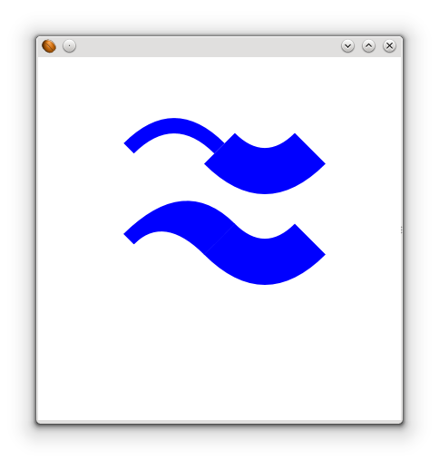
Best regards,
Matthias
[Updated on: Fri, 17 June 2016 08:34] Report message to a moderator |
|
|
| Re: [GEF4] Calculation of stroke outline in model [message #1735380 is a reply to message #1735302] |
Sat, 18 June 2016 00:00 |
|
Awesome, that looks great. I also tried the same approach on calculating the fat outline - it's pretty good except for the degenerate case where the control point is actually on the curve (i.e. it's really a straight line). In that case I just calculated the offset as the midpoint between the two curve offset points. Apart from that, it gives a really good fat outline - on very wide lines with sharp curves, it overestimates the control points just a bit, but otherwise a very good fit, and with excellent performance.
Colin Sharples
CTG Games Ltd
Wellington, New Zealand
|
|
|
Goto Forum:
Current Time: Thu Sep 26 18:26:09 GMT 2024
Powered by FUDForum. Page generated in 0.04201 seconds |
") ]
]  Search
 Help
Help Register
 Login
Login Home
Home