SVG visualization example
To illustrate how to make an SVG visualization, a simple generator, buffer, server, buffer, server, exit (GBSBSE) process line is used. Below the generator and exit process definitions, and the model:
proc G(chan! real to; real ptime):
    int n = 0;

    while n < 100:
        to!time; delay ptime; n = n + 1
    end
end

proc E(chan? real from):
    real x;

    while true:
        from?x
    end
end

model M():
    list(3) chan real c;
    list(2) chan real bs;

    run G(c[0], 1.1),

        B(0, c[0], bs[0], 3),
        S(0, bs[0], c[1], 1.0, exponential(10.0), exponential(4.0)),

        B(1, c[1], bs[1], 3),
        S(1, bs[1], c[2], 0.9, exponential(10.0), exponential(4.0)),

        E(c[2]);
end
This system should be visualized, where the number of items in each buffer should be displayed, and the state of each server (waiting for input, processing, or waiting for output) should also be shown. The gbse.svg SVG file was made for this purpose, which looks like
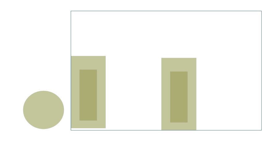
in an editor. The black rectangle represents the displayed area when the visualization is running. It has two light-green rectangles in it, representing the first and second buffer. The darker green rectangles inside will vary in height to show the number of items in each buffer.
The circle at the left of the displayed area is never displayed in the visualization. However, each server makes a copy of it, and places it at an appropriate position in the display. While for two servers, one could just as well perform the copying beforehand, as was done with the buffer graphics, but the copying technique demonstrates how to scale visualizations for displaying a larger number of items without a lot of effort.
Buffer visualization
The left darker green rectangle has an id with value buf0, while the right rectangle has an id containing buf1. Through the id, you can access the properties, in this case, the height, for example attr buf0.height = 50. This will set the height property of the SVG element named buf0 to 50.
The SVG visualization is not in the Chi model itself, it is an external entity. You access it by opening a 'file', and writing the commands such as above, as lines of text. The code of the buffer is shown below.
proc B(int num; chan? real from; chan! real to; int cap):
    list real xs;
    real x;
    file f = open("SVG:gbse.svg", "w");

    while true:
        select size(xs) > 0, to!xs[0]:
            xs = xs[1:];
        alt size(xs) < cap, from?x:
            xs = xs + [x]
        end
        writeln(f, "attr buf%d.height = %d", num, size(xs) * 50);
    end
    close(f);
end
It is a normal finite buffer process, except for three additional lines. The first change is the file f = open("SVG:gbse.svg", "w"); line. It creates a connection to the SVG visualization due to the SVG: prefix of the file name. gbse.svg is the name of the .svg file described above. The 'file' should be opened for writing (since you will be sending commands to it).
The second line is the writeln(f, "attr buf%d.height = %d", num, size(xs) * 50); line, which constructs a line of text to set the height of the darker green rectangle to a value proportional to the number of elements in the buffer. There is however a vertical coordinate trick needed to make it all work.
The third line is the close(f); line at the end of the process. It closes the connection to the SVG visualization.
Vertical coordinates trickery
In SVG, the vertical coordinates run from the top of the screen to the bottom. If you just draw a rectangle, its base position (x,y) is at the top-left corner, with width going to the right of the screen, and height towards the bottom. In other words, if you change the height of a simple SVG rectangle by a program like the buffer process, the rectangle will grow downwards instead of upwards!
To make it grow upwards instead, you can
-
change both the
heightand theycoordinate of the rectangle at the same time (you move the top of the rectangle in opposite direction with its growth in height, so it looks like the rectangle grows upwards), or -
flip the coordinate system of the rectangle by inserting a '180 degrees rotation' transformation around the rectangle (you tell SVG to draw the rectangle 'upside down', thus if you make it higher, it grows downwards, but the flipped coordinate displays it as growth upwards.
Server process
The server process code looks as follows (ignore all the writeln lines for now).
proc S(int num; chan? real from; chan! real to; real ptime; dist real up, down):
    real event, x;
    file f = open("SVG:gbse.svg", "w");

    writeln(f, "copy server, , _x%d", num);
    writeln(f, "absmove s_x%d (%d, 325)", num, num*420+150);

    while true:
        event = time + sample up;

        # Up; process items.
        while event > time:
            writeln(f, "attr s_x%d.fill=yellow", num);
            from?x;
            writeln(f, "attr s_x%d.fill=green", num);
            delay ptime;
            writeln(f, "attr s_x%d.fill=magenta", num);
            to!x;
        end

        # Down; repair machine.
        writeln(f, "attr s_x%d.fill=red", num);
        delay sample down;
    end
    close(f);
end
The server runs forever, starting with sampling how long it will be up (event = time + sample up). Until it has reached that time (while event > time:), it cycles through getting a product, processing it for uptime time units, and sending the product out again. After a few cycles, it has reached the event time, goes down, and waits for repair (delay sample down;). Once the machine is repaired it starts again. Visualization of the servers is discussed below.
Visualizing the server
A server is to be visualized with a circle that changes color depending on what the server is doing. Yellow means it is waiting for a product, green means processing, magenta means it is waiting to pass the finished product to the next station, and red means the machine is down. After repairing, it will continue processing.
As with the buffer process, the SVG visualization first opens a file connection to the visualizer and the SVG file with the file f = open("SVG:gbse.svg", "w"); line. The filename of the .svg file must be the same as with the buffer process (the visualizer can only show one SVG file at a time).
To display server state in the SVG visualization, we need a circle (called arc in SVG) named s_0 and s_1 (for server 0 and server 1), positioned behind its buffer. If there are not too many servers, and their number is fixed, one could simply add those arcs to the SVG file and be done with it. However, if you have a lot of servers, or you don’t know in advance how many you will have, you cannot add them beforehand, you need to construct the SVG elements 'on the fly'.
Copying SVG elements
For showing the server states, arcs named s_0 and s_1 are required in SVG, which are created by copying and moving an SVG element. In this case, a server is represented by just one SVG element, so you can copy and move that one element. In general however, you want to copy several elements at the same time (for example you might want to copy graphical elements to display a work station, a server with its buffer).
SVG has group elements, where you can put any number of (graphical) elements inside. When you copy a group, you copy its entire contents. The gbse.svg file as a group called server, containing an arc element called s. The server group is copied and moved, which causes the arc element to be copied and moved as well.
Inside an SVG file, each element must have a unique id, that is, each element must have a unique name. When making a copy, the copied elements must thus also be given a new name. The entire operation is performed with sending a copy [node], [prefix], [suffix] command to the SVG visualizer. It takes the element named [node], and makes a full copy of it (all elements inside it are also copied). For each copied element the [prefix] is added in front of its id name, and the [suffix] is added behind it.
The writeln(f, "copy server, , _x%d", num); line in the Chi simulation performs the copy operation for the servers. It takes the server group element (which contains an s arc element), and adds nothing in front of the names (there is no text between the first and the second comma). It appends the names with _x0 for the first server, and _x1 for the second server. The result is thus a copy of the server group, called server_x0 or server_x1, containing an arc s_x0 respectively s_x1.
Note that the copy command performs copying, and nothing else. Since the copied element is exactly at the same position as the original, you don’t see copies. This is however fixed by a move command explained next.
Moving SVG elements
You often want to position an SVG element at some point in the display. The simplest way to do that is to change its x and y attributes, much like the height attribute of the buffer rectangle was modified. Another solution is to perform a relative move, using transform/translate.
This works, until you add a transformation element that changes the coordinate system. Sometimes you do this consciously, for example adding a 'flip' transformation to fix the vertical coordinates. At other times the SVG editor may insert one, for example when you rotate or scale some part of the drawing.
The Chi SVG visualizer has a absmove [node] ([xpos], [ypos]) command to handle this case. It computes a transformation to get the top-left corner of the element named [node] at position ([xpos], [ypos]). Keep in mind that the vertical coordinate starts at the top, and goes down.
There are limitations to this command, in some case it may fail (see the reference manual for details about the command). It is recommended to use this command one time on an element to move it to a known base position. Once it is at a known position, change the x and y coordinates of a child element (to avoid disturbing the base position), to move relative to that base position. Another solution is to perform a relative move, using transform/translate.
In the Chi simulation, the writeln(f, "absmove s_x%d (%d, 325)", num, num*420+150); line moves the copied s_x0 and s_x1 arcs to the right position in the display.
With the arcs in the right position in the display, the servers can display their activities by changing the color of the fill attribute.