
ATL Use Case - Model Driven Performance Engineering: From UML/SPT to AnyLogic

ATL Logo

This use case presents a transformation from annotated UML2 activity diagrams to AnyLogic simulation models.

Keywords

UML2, Simulation, Model Driven Performance Engineering, SPT

Overview

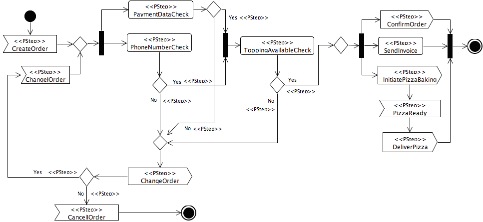
In this case study we present a transformation from annotated UML activity diagrams to AnyLogic simulation models. The actions and control flows in activity diagrams are annotated with performance information utilizing the UML profile for schedulability, performance, and timing (SPT). This information is used to generate a simulation model that can be executed by the AnyLogic simulation tool from XJ Technologies. Such simulations can help to identify performance issues early in a software design process.

When designing software, system behavior can be modeled using UML by utilizing, for instance, activity diagrams. To lower costs and risks, it is desirable to run analysis on the modeled system before it is actually implemented.
However, in order to execute useful analysis, certain performance information has to be available. For instance, approximations of the time it would take to perform certain actions. Such information could be derived from knowledge and experience.
Annotating performance information on UML models has been standardized in the SPT profile and its successor the MARTE profile. In this use case, we use a simplified version of SPT that includes the parts of the specification required here.
As an example, we consider a high level description of an online pizza ordering process illustrated below.


The pizza ordering process as activity diagram

In the diagram, several elements are stereotyped with the PStep stereotype. It is defined in the SPT profile and identifies one processing step that has performance properties. It defines a set of stereotype attributes that can be used to set concrete performance parameters. The values set for the CreateOrder action are shown below.


Performance attributes of the CreateOrder action

Two of the properties are set to meaningful values here: the Host Execution Demand and the Repetition.
The Host Execution Demand is set for every action in the diagram. It depicts the time required to perform the action. It is also indicated that the value is a mean (mean) value, which is assumed (asmd).
The Repetition attribute is utilized to set arrival rates. It is set for actions succeeding an initial node.
Not illustrated, but also utilized, is the Probability attribute. It is set on control flows that originate in decision nodes. It depicts the probability that a certain path is chosen by the decision.
Annotated UML activity diagrams act as input to the transformation. The output of the transformation is an AnyLogic simulation model. AnyLogic is a simulation engine that can run simulations to analyze systems and provides visual representation of the running simulation. The latter supports the understanding of problem sources, especially in early system design.
In AnyLogic, one can define libraries of elements that participate in simulations. Instances of these library elements can interact through messages that are passed through ports and connectors. We have created such a library containing elements known from activity diagrams. For these elements, we have defined the simulation semantics and visual representations.
The result of the transformation is a simulation using elements from the activity diagram library, configuring and connecting them according to the information obtained from the input activity diagram. Below, a snapshot of the running simulation is presented.


Running simulation in AnyLogic

The figure shows the status of a system after a certain running time. Green coloring indicates that an action is currently active. In front of the actions, red bars show the amount of requests waiting for processing. In the figure, one notices the fairly high amount of waiting requests at the PhoneNumberCheck action. This hints at a possible bottleneck in the design.
In order to have an appropriate visual representation in AnyLogic, we not only take the abstract syntax of an activity (i.e., the UML model) but also the concrete syntax (i.e., the UML diagram) as input for the transformation.
As UML modeling tool, we used TOPCASED, which stores the concrete syntax of models as diagram interchange models. Thus, the concrete syntax information is technically another model and we therefore have two input models for the transformation: One containing the actual model (conformant to the UML2 metamodel) and one containing the concrete diagram syntax (conformant to TOPCASED diagram interchange metamodel).
The transformation result is a simulation model conforming to a simplified AnyLogic metamodel. Another trivial transformation together with ATL XML extractor is used to transform the model into the proprietary XML format of AnyLogic, which can then be opened, compiled, and run by the simulation engine. The figure below illustrates the transformation process with the models and metamodels involved.


Overall Transformation Process

In order to execute the use case, Eclipse UML2 and TOPCASED should be installed in an Eclipse environment. This will automatically make the UML2 and TOPCASED DI metamodels available to the transformation. Because the TOPCASED DI metamodel introduces some specific primitive types, an extended model handler is required for DI models. It can be found in the download section below and can be installed by putting it into the Eclipse plugin folder. All other metamodels and the example are contained in the scenario package.

Related Use Cases

None at the current time.

Download

Complete Scenario

ATL project containing all the resources allowing running the whole transformation scenario

Extended EMF Model Handler For ATL

Extended EMF model handler for ATL permitting dealing with non-standard primitive types

AnyLogic Metamodel

Metamodel for creating AnyLogic simulation models

Acknowledgement

The present work is being supported by the IST European MODELPLEX project (MODELing solution for comPLEX software systems, FP6-IP 34081).
General Information

Back to the top