| Element based edge source and target problem [message #1403747] |
Fri, 25 July 2014 20:02  |
 Arunkumar Ramaswamy Arunkumar Ramaswamy
Messages: 57
Registered: April 2014 |
Member |
|
|
I have a domain model for component-port-connector as shown in image.
I am trying to model the tool using sirius.
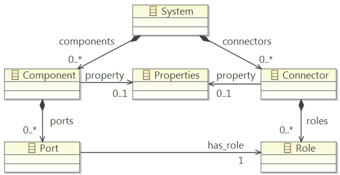
I created a container for Component and border node for port.
Note that there is no graphical element for the class Role in the diagram.
The issue is related to creating element based edge.
The diagram should show edge connecting ports (bordered nodes)
For element based edge i gave the properties as below
Domain Class: model.Connector
Source Mapping: Bordered Port
Target Mapping Bordered Port
While i could not see what to provide for source and target finder expressions.
whether it should return class Port or class Role?
Any help much appreciated.
Arun
[Updated on: Fri, 25 July 2014 20:04] Report message to a moderator |
|
|
| Re: Element based edge source and target problem [message #1403825 is a reply to message #1403747] |
Mon, 28 July 2014 07:42  |
|
Hi,
Le 25/07/2014 22:02, Arunkumar Ramaswamy a écrit :
> I have a domain model for component-port-connector as shown in image.
> I am trying to model the tool using sirius.
>
>
>
> I created a container for Component and border node for port.
> Note that there is no graphical element for the class Role in the diagram.
> The issue is related to creating element based edge.
> The diagram should show edge connecting ports (bordered nodes)
> For element based edge i gave the properties as below
> Domain Class: model.Connector
> Source Mapping: Bordered Port
> Target Mapping Bordered Port
> While i could not see what to provide for source and target finder expressions.
> whether is should return class Port or class Role?
>
You should put an expression whose allow to retrieve from a Connector
its source Port and its target Port. How do you link a Connector to its
source and target Port in your models ? If this is done by two Ports
which have some Role (referenced by has_role) and those 2 Role elements
are contained by the connector you want to display, you could try the
following expressions:
. source finder expression: [roles->first().eInverse(Port)/]
. target finde rexpression: [roles->last().eInverse(Port)/]
The eInverse() operation returns all the elements which have a reference
to an element [1]. From your screenshot, I assume that a Role could be
referenced only from a Port through the has_role reference which has no
eOpposite reference, so calling eInverse(Port) we retrieve all the Port
referencing the current Role. And I chose to take the first Role of a
Connector as its source Role, and the second one as its target Role.
Some remark about your scrrenshot: it seems your meta-model does not
have a EReference with containment=true to store your Properties EClass
(but your diagram might not show all the meta-model). So you might not
be able to add Properties element to your deomain model (or you add them
as root content of your model file ?)
> Any help much appreciated.
> Arun
>
>
Regards,
Maxime
[1]
https://wiki.eclipse.org/Acceleo/Acceleo_Operations_Reference#Non-standard_.2AEObject.2A_operations
Maxime Porhel - Obeo
Need training or professional services for Sirius?
http://www.obeodesigner.com/sirius
|
|
|
|
| Re: Element based edge source and target problem [message #1404705 is a reply to message #1404650] |
Tue, 05 August 2014 07:50 |
|
Hi,
Le 04/08/2014 19:02, Arunkumar Ramaswamy a écrit :
> Thanks Maxime for your reply.
> But I didnt manage to solve the problem
> Here is my updated metamodel
>
>
>
> I am trying to create a element based edge that represent the element: Connector and Role
>
> Here is my screenshot of property view of element based edge
>
It seems ok to , could you try to replace eInverse(Port) by
eInverse(robotmodel::Port) to make Acceleo use the the qualified name ?
You could also
. open you domain model in its standard EMF generatered tree editor,
. open the Acceleo Model To text > Interpreter view
. Select the Sirius interpreter mode
. In your tree domain editor, select your connector
. You can use the interpreter view to write your expression and test it.
>
>
> I also tried with source and target finder expression as
> [self.eGet('role')->first().eInverse(Port)/]
> [self.eGet('role')->last().eInverse(Port)/]
>
> Still I did not see any edges in my diagram
>
> Here is the snapshot of diagram editor that loaded an existing model. I can see only components and ports, while connectors are missing.
>
> Any help much appreciated
>
> Arun
>
>
Regards,
Maxime
Maxime Porhel - Obeo
Need training or professional services for Sirius?
http://www.obeodesigner.com/sirius
|
|
|
|
| Re: Element based edge source and target problem [message #1404723 is a reply to message #1404713] |
Tue, 05 August 2014 09:44 |
|
Le 05/08/2014 11:04, Arunkumar Ramaswamy a écrit :
> Thanks Maxime
>
> I tried the interpreter by selecting the model elements in editor view.
> still this did not work eInverse(robotmodel::Port) I tested the below
> query by selecting the port element. Even this one returns false.
> [self.oclIsTypeOf(robotmodel::Port)/]
I wrote 'robotmodel::Port' when I saw your screenshot on which you put
'robotmodel::Connector', could you check your package name ? Did you set
the domain class using the completion ? (You could restrict the
metamodels used in your diagram description by selecting the metamodels
to use in the corresponding property tab when the DiagramDescription is
selected in the VSM editor.
>
> I dont know where i am making the mistake.
> Let me know if you can help me
>
> Thanks
> Arun
>
>
Regards,
Maxime
Maxime Porhel - Obeo
Need training or professional services for Sirius?
http://www.obeodesigner.com/sirius
|
|
|
|
| Re: Element based edge source and target problem [message #1404987 is a reply to message #1404726] |
Wed, 06 August 2014 09:55 |
|
Le 05/08/2014 12:12, Arunkumar Ramaswamy a écrit :
> Before, I deployed my ecore files, edit, editor as jar files and
> deployed in dropins folder and was using the same instance of eclipse
> to design my tool using sirius.
Note that you need to restart your Eclipse each time you deploy a new
version of the plug-ins for them to be taken into account.
> Is there a better way to deploy my ecore metamodels so that i can
> use the same eclipse instance for tool development?
Not really.
To test your modeler you need an instance of your metamodel, and for
that you need the corresponding plug-ins to be generated and installed
[1]. Usually it is not a problem because when you are advanced enough in
a project to start creating graphical tooling, the metamodel(s) are
usually stable enough that you install or update the corresponding
plug-ins very rarely.
It is more annoying when testing and "playing" with small examples where
you want to iterate both on the metamodel and the representation, but
for this case the best way is usually to use a separate runtime for the
model instances and the representations. The price is an occasional
restart of the runtime when you change the metamodel.
Regards,
Pierre-Charles David
[1] This is not strictly true, EMF itself supports the creation of
"dynamic instances" using only the ecore and no Java code generated from
it and deployed. However this is not well supported by Sirius, and
possibly by other parts of the stack we use, so it is not recommended.
Pierre-Charles David - Obeo
Need training or professional services for Sirius?
http://www.obeodesigner.com/sirius
|
|
|
|
| Re: Element based edge source and target problem [message #1405923 is a reply to message #1405155] |
Fri, 08 August 2014 14:01 |
|
Le 06/08/2014 20:13, Arunkumar Ramaswamy a écrit :
> I did exactly as you said.
> I created the graphical tool using sirius in the runtime instance. It is
> working perfectly.
> Then I tried to deploy the plugin. I created deployable jar plugins of
> metamodel, .edit and .editor projects from normal instance of eclipse
> and jar plugins of VSP from the runtime instance of eclipse. I placed
> all the four jar files in dropins directory and restarted the eclipse.
> Now I created a sample model using the builtin tree editor and created
> the viewpoints, representations - diagrams. But the tool doesn't behave
> properly, For eg: edges are not seen, labels are not populated but i can
> see the nodes. These things worked as expected in the runtime instance.
> Please let me know where I am making the mistake
Difficult to guess without more details.
Things to look at:
* Do you have any errors in the error log with the problemtic scenario?
* Check that all the plug-ins you put in the dropins folder are actually
installed, and in the latest versions (especially if you iterated on
some plugins). Dropins is not a recommended way to install plug-ins: it
is brittle and gives zero feeback when it can't install something.
* Try to find some commonality between the definition of the elements
which do not work (edges and labels) compared to the ones that do. For
example do you Acceleo queries in one case and raw feature: access in
others?
Pierre-Charles David - Obeo
Need training or professional services for Sirius?
http://www.obeodesigner.com/sirius
|
|
|
Powered by
FUDForum. Page generated in 0.02075 seconds
") ]
]  Search
 Help
Help Register
 Login
Login Home
Home