Home » Eclipse Projects » Sirius » Sequence Diagram(Move within the Lifeline-Layout)
| Sequence Diagram [message #1848028] |
Wed, 17 November 2021 15:17  |
 Antonio Garmendia Antonio Garmendia
Messages: 93
Registered: May 2014 |
Member |
|
|
Hi all,
Recently, I just start with some tutorials regarding the implementation of a sequence diagram for your custom language using Sirius. Basically, inspecting the example of the interactions and [1].
Currently, I am trying to develop a language that should look something like this:
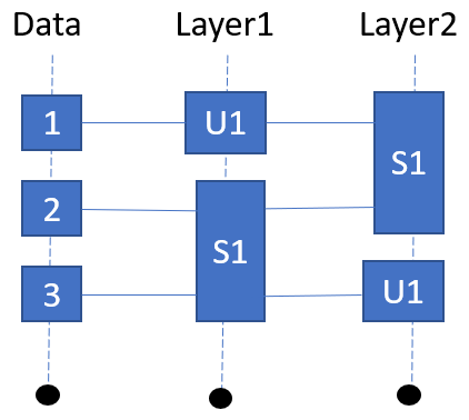
Basically, it is data that passes from one layer to another. The root is the Pipeline that contains the layers and the layers contains the different methods. Each method should reference one Data or a set of Data.
At this moment, I have two problems:
1. I am not able to move the data elements within the lifetime. Right now, the last data element is only shown on the diagram. I think that I do not understand well the endsOrdering and the Instance Role Ordering :-/.
2.It would be possible connect/disconnect elements by the size. If I have a representation like in the figure and I reduce the size of Layer1/S1 element then, I will like to remove the connection of Data3 and S1. Is that possible?
I uploaded the pipeline example, just in case someone has time to take a look at it.
I am using Sirius 6.5.1.
Thanks for any help!
Kind regards,
Anthony
[1] https://www.eclipse.org/sirius/doc/specifier/sequences/Sequence%20Diagrams.html
|
|
|
| Re: Sequence Diagram [message #1848043 is a reply to message #1848028] |
Thu, 18 November 2021 09:37  |
|
Hi Anthony,
The instanceRole ordering is used to synchronize the graphical horizontal layout (order of the lifelines) and their semantic order in the model.
The ends ordering is used as a global ordering to synchronize the graphical vertical layout (order of all displayed "events": start/stop of executions, messages, ...) and their semantic order in the model.
You will not have the possibility to align execution starts between two lifelines: the layout will always put at least 5pixel : we consider that two "event ends" cannot occur at the same "time"/y.
1.: this means that you might have an issue around you mappings and orderings.
2: the "reorder" tools are called when you move/resize elements, if the ordering has changed, one lead might be to add additional cleanup of the model it those tools.
I will try to take a look to your zip.
Maxime Porhel - Obeo
Need training or professional services for Sirius?
http://www.obeodesigner.com/sirius
|
|
|
| Re: Sequence Diagram [message #1848044 is a reply to message #1848043] |
Thu, 18 November 2021 10:18 |
|
Hi Anthony,
Your starting/finishing ends expressions for the execution mappings should reference the elements you consider as start/end events of the current pipeline::Method.
Your SequenceDiagramDescription::endsOrdering is currently set to aql:self : it shoudl corresponds to a global ordering of all start/ends of the elements which will be created by the Execution mappings (and also any Sequence specific mappings with the ends expressions).
In order to have Sequence correctly working, you need to have unique start/end for each "execution" and those elements globally ordered in the SequenceDiagramDescription endsOrdering expression result.
If you switch the outline to tree mode, you will see one item for each graphical element : the diagram content seems correct, only the Sequence Layout is broken : you need to fix the orderings and ends expressions.
Then I see that you have defined an Edge mapping, it will not be layouted by Sequence, only "Message" mappings are handled.
Your Viewpoint might need to be renamed : PepilineViewpoint ->PipelineViewpoint.
Regards,
Maxime Porhel - Obeo
Need training or professional services for Sirius?
http://www.obeodesigner.com/sirius
|
|
|
| Re: Sequence Diagram [message #1848096 is a reply to message #1848044] |
Fri, 19 November 2021 14:50 |
Antonio Garmendia
Messages: 93
Registered: May 2014 |
Member |
|
|
Hi Maxime,
Thanks a lot! Sorry for the late reply, but I am still struggling with some concepts that unfortunately I still do not understand well. My doubts are the following:
1. SequenceDiagramDescription::endsOrdering. I am struggling in trying to debug the interactions example, but unfortunately I still do not understand how exactly it works. I still do not know what I should return here. So, Imagine that I have a model like the above figure, then, What I should return in the endsordering? Something like this: Data1, Layer1/U1, Layer2/S1, Data2, Layer1/S1, Layer2/S1, Data3, Layer1/S1, Layer2/U1.
2. My other doubt is regarding the execution of the DataNode. What I should return in Starting End Expression and Finishing End Expression? It shoud be something like this for Data1:
-Starting End Expression: self
-Finishing End Expression: Layer1/U1
I would say that this is also one of my problems.
Hopefully, you can understand my questions.
Thanks!
Kind regards,
Antonio
|
|
|
| Re: Sequence Diagram [message #1848297 is a reply to message #1848096] |
Fri, 26 November 2021 18:01 |
|
Hi Antonio,
The Sequence dialect makes the assumption that you have data in your model to identify those ends.
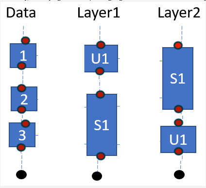
I have represented the ends on a draft modification of your image:
- each Sequence event (here only executions) has a starting end and a finishing end represented as red and blue disks.
- the global ordering expected as result of SequenceDiagramDescription::endsOrdering would be :
- 1.start,
- u1_fromLayer1.start,
- S1_fromLayer.start,
- 1.end
- u1_fromLayer1.start,
- 2.start
- S1_fromLayer1.start
- S1_fromLayer2.end
- 3.start
- u1_fromLayer1.start
- 3.end
- u1_fromLayer2.start
- S1_fromLayer1.end:
Sirius Sequence diagrams will not be able to align your executions : it makes the assumption that there correspond to different time event : there will be a 5pix minimum gap between each "end".
Regards
Maxime Porhel - Obeo
Need training or professional services for Sirius?
http://www.obeodesigner.com/sirius
[Updated on: Fri, 26 November 2021 18:02] Report message to a moderator |
|
| | |
Goto Forum:
Current Time: Fri Apr 19 21:27:42 GMT 2024
Powered by FUDForum. Page generated in 0.02878 seconds |
") ]
]  Search
 Help
Help Register
 Login
Login Home
Home