Simulink code generation and simulation example
The Simulink C S-Function code generation can generate Simulink C code from a CIF specification. Here an example is given to demonstrate how the code generator can be used to control a model in Simulink.
Matlab and Simulink are products owned by Mathworks.
System to control
The system to control is a simple water tank, as shown below.

The water in the tank has volume V. At the bottom of the tank is a pipe where water flows away with speed Qo. At the top is a pipe with valve n that can be open or closed. The Qi variable denotes the speed of water flowing into the tank. The equations that hold in this system are:
Qi = n * 5
Qo = sqrt(V)
V' = Qi - Qo
By switching n on or off, a controller can control the amount of water flowing into the tank, and with that, control the volume V. The objective is to keep the volume between 2 and 10.
Controller in CIF
A switching controller will be sufficient to control this system. In CIF that results in a tank_ctrl.cif file containing:
event open_valve;

automaton controller:
    disc int n = 0;
    input real V;

    location closed:
        initial;
        edge open_valve when V <= 2 do n := 1 goto opened;

    location opened:
        edge when V >= 10 do n := 0 goto closed;
end
The controller has the control variable n, and input variable V. When the volume of the tank is below 2, n is set to 1, which turns on the inflow. When the volume of the tank is high enough, n is set to 0 which turns the inflow off.
Generating Simulink C code
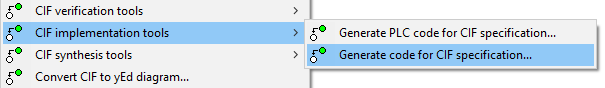
To simulate the controlled system in Simulink, the code generator tool can produce C code for Simulink that can be used in a Simulink System SFunction block. Convert the CIF model to C for Simulink with the code generation tool, by selecting the code generation tool from the menu under the right mouse button:
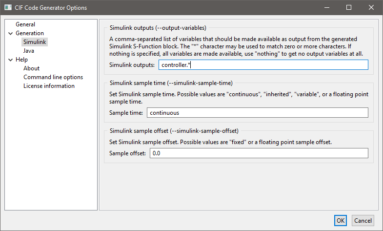
By default, you will get all internal variables at the output of the SFunction, which is often too much. The Simulink Generation tab allows precise definition of what output variables should be added, in this case all variables in the controller automaton. (Input variables are never made available from the CIF SFunction block, as they are already available in Simulink.)
After clicking OK, the CIF model is translated to C code. Code generation from the tank_ctrl.cif files results in two output files. The tank_ctrl.c file contains the generated C source code. The tank_ctrl_report.txt is a text file describing the data of the generated SFunction code:
Input/output report of the tank_ctrl.cif SFunction.

During code generation, CIF variables are made available in the Simulink vectors.
This report lists the variables in each vector, along with their index number.

Modes
-----
controller 1

Continuous states
-----------------
time 1

Inputs
------
controller.V 1

Outputs
-------
controller.n 1
The report shows which CIF variables are available at each vector. The Inputs and Outputs are the most interesting. Here it shows that V is the only input variable, n is the only output variable, and they are both the first value in their vector. This is what you would expect for such a small system. With bigger systems, the index numbers are much more useful for making proper connections in Simulink.
And this concludes the CIF part of this example, next step is setting things up in Matlab/Simulink.
Simulation in Simulink
After starting Matlab, and moving to the correct directory, you get a display like:
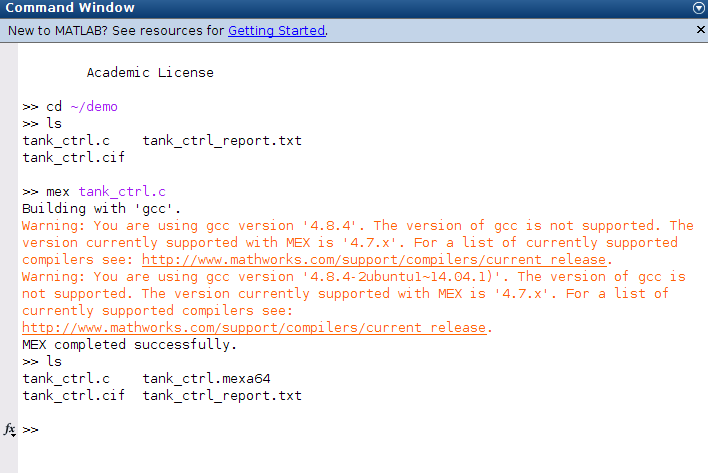
You can see the files present in the directory, as you would expect. In Matlab, the generated C code is compiled with the Matlab Mex compiler:
mex tank_ctrl.cHere, the compiler prints a warning about the wrong compiler version, this may be different at your system.
The result of the compilation is a tank_ctrl.mexa64 file at a 64 bit system. If you use a 32 bit system, the filename extension is different.
The compiled CIF controller can be used in a Simulink System SFunction block, as shown below.

In the middle the equations are modeled. The output of the equations is V, which is fed into the S-Function block with the CIF controller at the top. The controller computes n which is an input for the equations.
At the bottom, a scope is attached that produces the following picture.
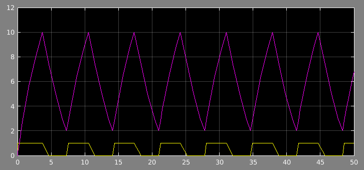
The volume fluctuates between 2 and 10, at the bottom is the control signal n.