Synthesis-based engineering in practice example
CIF supports the entire development process for synthesis-based engineering of supervisory controllers. The steps involved are described in the section on synthesis-based engineering in practice. However, here we focus on specification, supervisory controller synthesis, simulation and code generation.
We consider how a controller can be developed for the synthesis-based engineering example. This example is one of the many CIF examples. See the CIF examples section for how to import them into your Eclipse ESCET IDE, to experiment with them yourself. After importing the examples project into your IDE, you can find this example in the project’s synthesis/fifo folder.
Plant specification
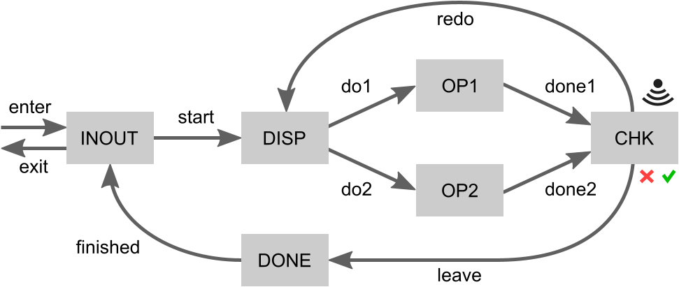
First, we’ll specify the plants (file fifo.plants.cif). Consider again the following figure that visualizes the example system:
Events
Each of the arrows indicates a movement of products. We can model each arrow as a controllable event that the supervisor can control. The checker (CHK) may indicate that a product was processed successfully or that it failed, which we can model as uncontrollable events. This leads to the following event declarations:
controllable c_enter;
controllable ProductId c_start;
controllable ProductId c_do1;
controllable ProductId c_do2;
controllable ProductId c_done1;
controllable ProductId c_done2;
uncontrollable u_success;
uncontrollable u_failure;
controllable ProductId c_redo;
controllable ProductId c_leave;
controllable ProductId c_finished;
controllable c_exit;
Product identifiers
To be able to express the example’s FIFO requirement, we must keep track of product identifiers (ids). A product may enter the system, after which it gets its id. As products move through the system, their id is passed along. Hence, most of the events are channels that communicate a ProductId. This is a custom type, defined as follows:
const int MAX_NR_OF_PRODS = 5;
type ProductId = int[0 .. MAX_NR_OF_PRODS - 1];
CIF can only perform synthesis on specifications where types have a finite domain. We therefore define a maximum number of products (MAX_NR_OF_PRODS) that may be in the system. Product ids are then integer numbers in the range [0 .. MAX_NR_OF_PRODS - 1], with both bounds being inclusive. This allows each product in the system to have a unique id.
The INOUT place
Each of the system’s places that can holds a product is modeled as a plant automaton.
First we model the INOUT place:
plant INOUT:
  disc ProductId nextId = 0;
  disc ProductId curId = 0;
  disc ProductId lastExitId = MAX_NR_OF_PRODS - 1;
  disc int[0..MAX_NR_OF_PRODS] cnt = 0;

  location Idle:
    initial;
    marked;
    edge c_enter when cnt < MAX_NR_OF_PRODS do curId := nextId, nextId := (nextId + 1) mod MAX_NR_OF_PRODS, cnt := cnt + 1 goto NewProduct;
    edge c_finished? do curId := ? goto FinishedProduct;

  location NewProduct:
    edge c_start!curId do curId := 0 goto Idle;

  location FinishedProduct:
    edge c_exit do lastExitId := curId, curId := 0, cnt := cnt - 1 goto Idle;
end-
Variable
nextIdkeeps track of the product id to use for the next product that enters the system. The first product to enter the system gets id0. -
Variable
curIdrepresents the product id of the product that is currently located at the INOUT place. However, its value is irrelevant when there is no product at the INOUT place. -
Variable
lastExitIdkeeps track of the last product that exited the system. Given that products must enter and exit in FIFO order, and that the first product to enter gets id0,lastExitIdis initialized to the largest possible product id. -
Variable
cntcounts the number of products currently in the system. As initially there are no products in the system, it is initialized to0. The count is used to ensureMAX_NR_OF_PRODScan be honored.
A product may only enter (by event c_enter) if the maximum number of products is not yet exceeded (cnt < MAX_NR_OF_PRODS). The product then gets assigned the next product id (curId := nextId), it being a newly entered product currently located at the INOUT place. As the next product id has then been used, it will be incremented by one to ensure the next product again gets a unique product id (nextId := (nextId + 1)). Given that the ProductId type only allows a finite number of ids, we loop around to avoid overflow (mod MAX_NR_OF_PRODS). We also update the number of products in the system (cnt := cnt + 1). The automaton then proceeds to its NewProduct location (goto NewProduct).
In the NewProduct location, processing of a product may start (event c_start) by sending it (c_start!) to the dispatcher (DISP). The product id is sent along (!curId) with this movement. After moving the product to the dispatcher, the INOUT place no longer holds a product (goto Idle). The product id is reset to zero (curId := 0). This is optional, but keeps the state space smaller, leading to more efficient synthesis.
While Idle the INOUT place may receive a finished product (c_finished?) from the DONE place. The product id of the currently present product is then updated to that of the received product (curId := ?). The automaton then proceeds to the FinishedProduct location.
There the product may exit (event c_exit) the system. It then becomes the last product to have exited the system (lastExitId := curId). There is then no longer a product at the INOUT place. Again the product id is reset to zero (curId := 0) to keep the state space smaller for efficient synthesis. As a product has left the system, the counter is also updated (cnt := cnt - 1).
The other places
For brevity, we’ll not explain the remaining places in as much detail as the INOUT place. We’ll discuss each automaton for each place briefly:
-
The dispatcher (DISP) receives products (
c_start?) from the INOUT place. It forwards them to either the first (OP1) or second (OP2) operator, withc_do1!curIdorc_do2!curId, respectively. -
The operators (OP1 and OP2) simply receive a product from the dispatcher (DISP) and forward it to the checker (CHK), after some processing.
-
The checker (CHK) receives a product from one of the operators (
c_done1?, c_done2?). It then determines whether the product was successfully processed (u_success) or processing has failed (u_failed). It forwards successfully processed products to the DONE place byc_leave, while failed products are sent back to the dispatcher (DISP) byc_redo. -
The DONE place simplify forwards products from the checker (CHK) to the INOUT place.
The FIFO requirement
With the plants specified, we specify the requirement (file fifo.plants_and_requirements.cif). We specify it in a separate file, to allow using the plant model for both synthesis and simulation, as described later in this section.
First, we import into this file the entire plant specification:
import "fifo.plants.cif";The requirement was given in natural language as:
-
Products must enter and exit the system in FIFO order.
We can easily model it as follows, using a requirement invariant:
requirement FIFO: INOUT.FinishedProduct => INOUT.curId = ((INOUT.lastExitId + 1) mod MAX_NR_OF_PRODS);If the INOUT place has a finished product (is in its FinishedProduct location), then a product is about to exit the system. We know the product id of the last product that exited (INOUT.lastExitId) and the product id of the product currently situated at the INOUT place (INOUT.curId). Products that enter the system get an id that is one higher than the previous product that entered (modulo the maximum number of products). The FIFO property can thus be ensured by requiring that when a product exits, it also has an id one higher than the last product that exited (again modulo the maximum number of products). From this, requirement FIFO follows directly.
Performing synthesis
We can automatically compute a supervisory controller by applying supervisory controller synthesis. For this, we’ll use the CIF data-based synthesis tool.
To be able to perform synthesis with the push of a button, a script is provided (file do1_synthesize.tooldef):
from "lib:cif" import *;

mkdir("generated", force=true);

cifdatasynth("fifo.plants_and_requirements.cif --forward-reach=true -mdebug -o generated/fifo.synthesized.cif");
It first imports the CIF tools. Then it ensures that directory named generated exists. It is thus created if it does not yet exist. Lastly, it invokes the CIF data-based synthesis tool on the file that contains the plants and requirements. It configures some options. Forward reachability is enabled for simpler resulting control conditions. It also enables debug output to be printed to the console, allowing to see what synthesis has done. Finally, it specifies that the synthesis result is to be saved to the fifo.synthesized.cif file in the generated directory.
To execute the script, right click it an choose Execute ToolDef or select the file and press F10.
Simulation model
To validate the system controlled by the synthesized supervisor, it can be useful to simulate it. We therefore specify a simulation model (file fifo.simulation.cif).
This model first imports the synthesized supervisor:
import "generated/fifo.synthesized.cif";It then specifies an SVG image to be used for visualization of the system:
svgfile "fifo.svg";The bulk of the specification consists of CIF/SVG output mappings that map the state of the plant model to properties of elements of the SVG image. Some of them ensure that text labels have the correct text, others ensure that boxes have the correct fill color, etc. Here are some examples:
svgout id "max-nr-of-prods" text              value <string>MAX_NR_OF_PRODS;
svgout id "inout-cur-txt"   text              value if INOUT.Idle: "-"        else <string>INOUT.curId end;
svgout id "inout"           attr "fill"       value if INOUT.Idle: COLOR_IDLE else COLOR_BUSY          end;
svgout id "chk-rslt"        attr "visibility" value if CHK.Idle:   "hidden"   else "visible"           end;
svgout id "chk-rslt"        attr "fill"       value switch CHK:
                                                      case Idle:    COLOR_IDLE
                                                      case Busy:    COLOR_BUSY
                                                      case Success: COLOR_SUCCESS
                                                      case Failure: COLOR_FAILURE
                                                    end;
The following figure shows a potential visualization of the state of the system during a simulation:
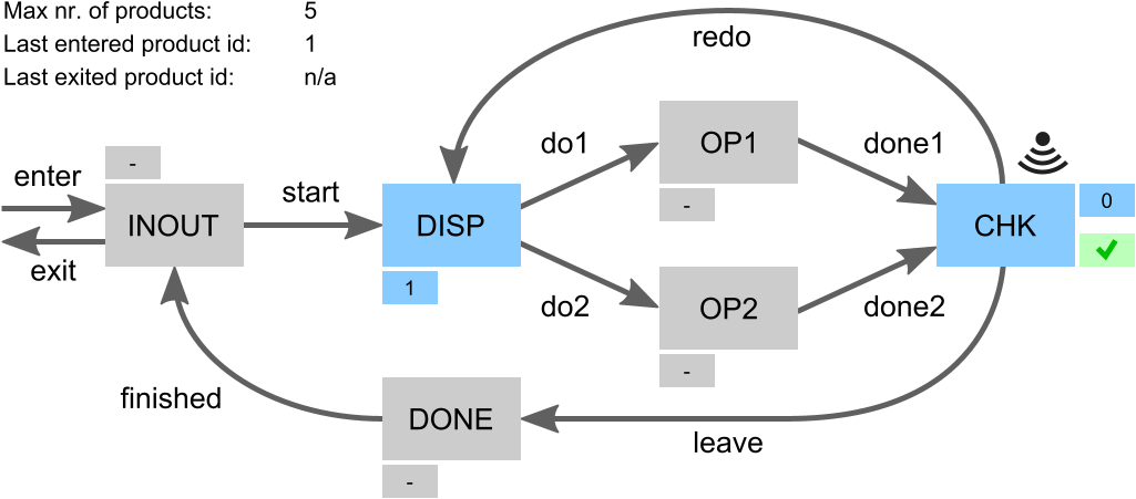
A place is gray if there is no product. The smaller box next to it is then also gray and indicates -, for no product. An occupied place is blue, with its smaller indicating the product id of the product that is present.
For the checker (CHK) a second small box is present. It is hidden if there is no product at the checker. If a product is present for which a check has not yet been done, then the box is blue and has a question mark. If the check has completed and the product was processed successfully, then the box is green and has a tick mark. If processing the product failed, then the box is red with a cross mark.
At the top left some additional information is provided. It indicates the maximum number of products that may be in the system, as configured via MAX_NR_OF_PRODS. It further indicates the product id of the last product that entered the system, or n/a if no product has entered the system yet. Finally, it indicates the product id of the last product that existed, as indicated by INOUT.lastExitId, or n/a if no product has exited thus far.
It can not be determined from the plant whether any products have entered or exited thus far, nor what is the product id of the last product that entered. To ensure this information is available to be used in the CIF/SVG output mappings, a monitor automaton is added to the simulation model that keep tracks of this information:
automaton monitors:
  disc bool anyInput = false;
  disc bool anyOutput = false;
  disc ProductId lastEnterId = 0;

  location:
    initial;
    edge c_enter do  anyInput := true, lastEnterId := INOUT.nextId;
    edge c_exit  do anyOutput := true;
end
As products enter (event c_enter) or exit (event c_exit) the variables are updated as needed. The variables are used in the CIF/SVG output mappings.
Simulating the supervised system
Similar to having a script to perform synthesis, a script is present to perform simulation (file do2_simulate.tooldef):
from "lib:cif" import *;
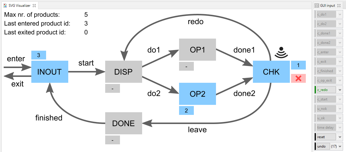
cifsim("fifo.simulation.cif -i gui");This script also imports the CIF tools. It then starts the CIF simulator. It configures some of the simulator’s options, among others to indicate the simulation model as model to simulate.
Start the script as before. Simulation will start and open two windows within the Eclipse ESCET IDE. One shows the visualization. The other allows events to be triggered in the system by clicking buttons. The following figure shows an example of what this could look like during a simulation:
Manually modeled supervisor
The example project also contains two other scripts. They can be used to check whether a manually modeled supervisor (file fifo.manually_modeled_supervisor.cif) has the same behavior as the synthesized supervisor. The first script (file do3_chk_cif.tooldef) performs this check using various CIF tools only. The second script (file do3_chk_mcrl2.tooldef) performs the same check using mCRL2.
Normally, one would not manually model the supervisor, and thus also not perform such checks. However, for this example we include them, as they may prove illustrative.
Code generation
Finally, from the synthesized supervisor an implementation of the controller may be automatically generated. CIF has tools to generate code for several programming languages.