Getting Started with APP4MC
General model content
The purpose of this session is to get familiar with the structure of the AMALTHEA model itself as well as the currently available editor. Therefore, a new model should be created in its own project using the following steps and content.
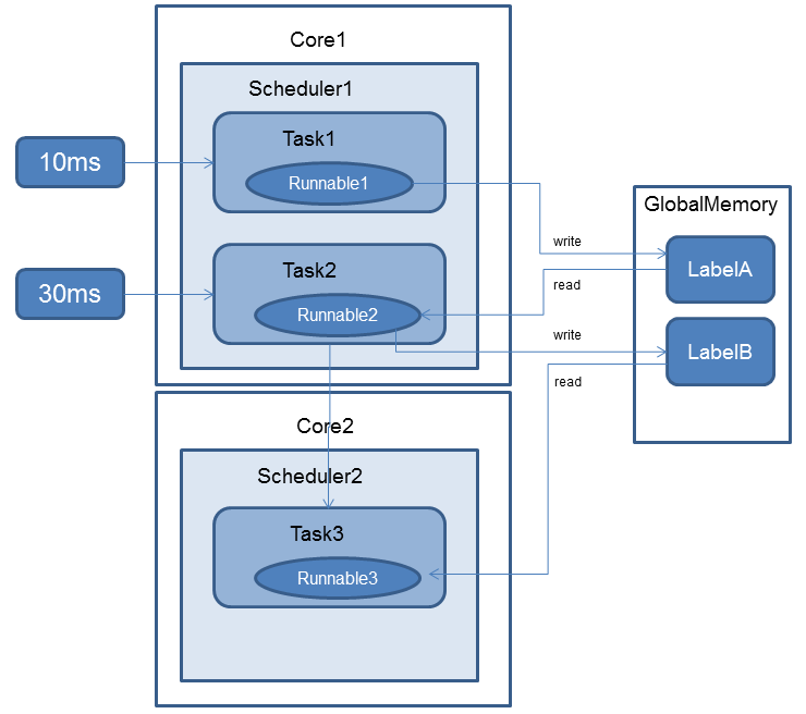
The following image is a simplified overview of the model that will be created in this session.
General model setup
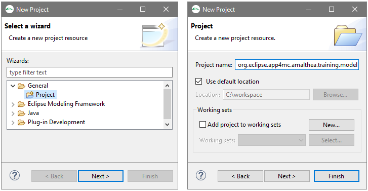
Create a new general project named org.eclipse.app4mc.amalthea.training.model
- From the File menu, select the item New > Project…
- On the first page of the wizard, expand the item General
and select Project. Then click Next
- On the second page of the wizard fill the Project name field
with org.eclipse.app4mc.amalthea.training.model, then click Finish
- The project created should appear in the Model Explorer view
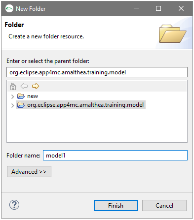
Create a new folder named “model1” inside the created project
- Select the created project
- In the context menu (right mouse button) select New > Folder
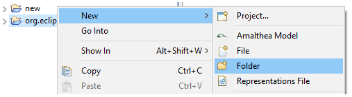
- Fill the text field Folder name with model1, then click Finish
Create a new AMALTHEA model
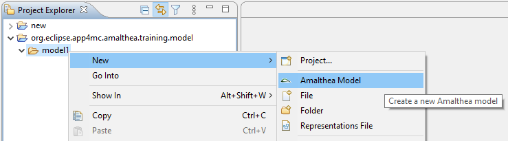
- Select the folder named model1
- In the context menu, select New > AMALTHEA Model
- In the dialog
- Keep the defaults (folder: “model1”, filename: “default.amxmi”)
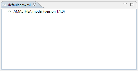
- Click Finish to create an empty model
- The model is created and the standard AMALTHEA tree editor can be opened.
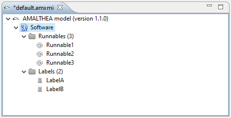
Adding software structure
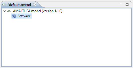
Right-click on the AMALTHEA model on the tree editor then select the menu item New Child > SW Model.
It will add a child node named Software to the model
Create a label named LabelA
- Select the Software item and right-click on New Child > Label.
This will add a new child under Labels.
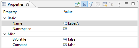
- Select this Label then click on the Properties tab below the tree editor to display the label properties.
- Click on the cell next to the property named Name and fill it with LabelA.
Press enter. The label item in the tree editor should be renamed LabelA.
Create a label named LabelB
Create a Runnable named Runnable1
- Select the Software item and right-click on New Child > Runnable.
This will add a new child under Runnables
- Select this Runnable then click on the Properties tab below the tree editor to name it Runnable1.
Create 2 additional runnables named respectively Runnable2 and Runnable3.
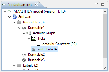
Select the runnable named Runnable1
- Right-click on New Child > Activity Graph
- Create * 20 constant ticks*
- From the context menu under Activity Graph, select New Child > Items > Ticks
- From the context menu under Ticks, select New Child > Default > Discrete Value Constant
- Select the child created then click on the Properties tab below the tree editor.
- Change the value of the Value property to 20
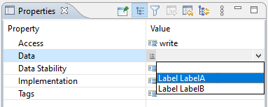
- Create a write access to LabelA
- Create another activity graph item by selecting the menu item New Child > Items > Label Access
- Select the child created then click on the Properties tab above the tree editor.
- Select for the Access property the value write
- Select for the Data property the value Label LabelA
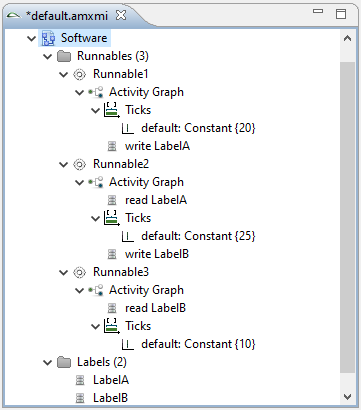
Expand the runnable named Runnable2 and, under its activity graph:
- Create a read access to LabelA
- Create 25 constant ticks
- Create a write access to LabelB
Expand the runnable named Runnable3 and, under its activity graph:
- Create a read access to LabelB
- Create 10 constant ticks
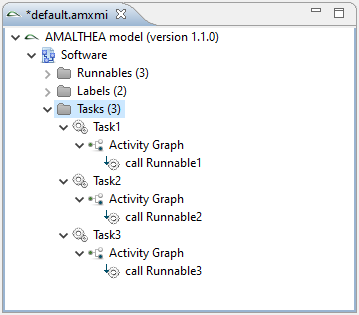
Create 3 tasks named respectively Task1, Task2 and Task3
- Select the Software item and right-click on New Child > Task.
- Select this Task then click on the Properties tab above the tree editor to name it Task1.
- Repeat these steps to create the 2 other tasks.
Create a CallGraph for the task Task1
- Right-click on the task named Task1 then select the menu item New Child > Activity Graph
- Create a Runnable Call to Runnable1
- Right-click on the activity graph
then select the menu item New Child > Items > Runnable Call
- Select the created child then click on the Properties tab
and set the Runnable property to Runnable Runnable1.
Create a CallGraph for the task Task2
- Right-click on the task named Task2 then select the menu item New Child > Activity Graph
- Create a Runnable Call to Runnable2
Create a CallGraph for the task Task3
- Right-click on the task named Task3 then select the menu item New Child > Activity Graph
- Create a Runnable Call to Runnable3
Add Stimuli to Tasks
Stimuli are describing the activation of Tasks.
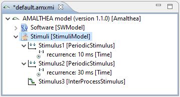
Create 3 Stimuli named Stimulus1, Stimulus2, and Stimulus3
- Right-click on the AMALTHEA model on the tree editor then select the menu item New Child > Stimuli Model.
It will add a child node named Stimuli to the model.
- Create a Periodic Stimuli named Stimulus1 and set the recurrence to 10ms
- Right-click on the Stimuli Model and select the menu item New Child > Stimuli > Periodic Stimulus
- Select the Child named by default Periodic Stimulus then rename it Stimulus1
- Right-click on the renamed stimulus and select the menu item New Child > Recurrence > Time
- Select the created Recurrence
- Set the value of the Unit property to ms
- Set the value of the Value property to 10
- Create a second Periodic Stimulus named *Stimulus2” and set the recurrence to 30ms
- Create an Inter Process Stimuli named Stimulus3
- Right-click on the Stimuli Model and select the menu item New Child > Stimuli > Inter Process Stimulus
- Select the Inter Process Stimulus node and name it Stimulus3
Add the Stimulus Stimulus1 to task Task1
- Retrieve and select the task Task1 which is located under the nodes AMALTHEA / Softwares / Tasks.
- On the Properties, select Stimuli and click on the button next to the field to open relationship dialog

- Select the Stimulus Periodic Stimulus Stimulus1
- Press the Add button
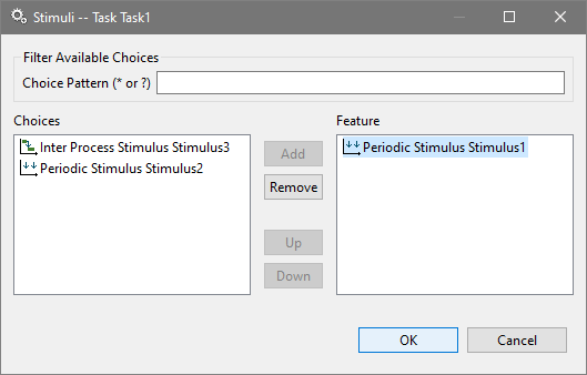
- Press OK to close the dialog.
Add the Stimulus Stimulus2 to task Task2
Add the Stimulus Stimulus3 to task Task3
Add an Interprocess Activation from Task2 to Task3
- Expand the Task2,
- Expand its Activity Graph node
- Right-click on the node and select the menu item New Child > Items > Inter Process Trigger
- Select the created node and in the Stimuli property, select the Stiuli named Inter Process Stimulus3
Create simple hardware model
In this section we are creating a simple hardware model with 2 cores and 1 global memory.
Right-click on the AMALTHEA model on the tree editor then select the menu item New Child > Hw Model.
It will add a child node named Hardware to the model
Create a new structure named DemoSystem
- Select the Hardware node previously created
- Right-click on the item then select the menu item New Child > Structure.
- Name the created item DemoSystem
- Set the StructureType to System
Create a new ECU named Ecu1
- Select the structure named DemoSystem
- Right-click on the item then select the menu item New Child > Structure.
- Name the created item Ecu1
- Set the StructureType to ECU
Add a microcontroller named MC1 to the ECU Ecu1
- Select the ECU Ecu1
- Right-click on the item then select the menu item New Child > Structure.
- Name the created item MC1
- Set the StructureType to Microcontroller
Create a memory definition named GlobalMemoryType
- Select the Hardware node under the AMALTHEA model node
- Right-click on the item then select the menu item New Child > Definitions > Memory Definition.
- Set the name to GlobalMemoryType
- Set the size of memory to 512 B (bytes)
- Set the type of memory to SRAM
Add a memory named GlobalMemory to MC1
- Select the microcontroller MC1
- Right-click on the item then select the menu item New Child > Module > Memory
- Name the created item GlobalMemory
- Set the definition to Memory Definition GlobalMemoryType
Create a frequency domain “100MHz”
- Select the Hardware node under the AMALTHEA model node
- Right-click on the item then select the menu item New Child > Domain > Frequency Domain.
- Name the created item 100MHz
- Right-click on the item then select the menu item New Child > Default Value
- Set value to 100.0 and unit to MHz
Create a frequency domain “200MHz”
Create a processing unit definition named CT1
- Select the Hardware node under the AMALTHEA model node
- Right-click on the item then select the menu item New Child > Definition > Processing Unit Definition
- Set the name to CT1
- Set Pu Type to CPU
Add a processing unit “Core1” to “MC1”
- Select the microcontroller MC1
- Right-click on the item then select the menu item New Child > Module > Processing Unit
- Name the created item Core1
- Set definition of “Core1” to “CT1”
- Set frequency domain of “Core1” to “100MHz”
Add a processing unit “Core2” to “MC1”
- Select the microcontroller MC1
- Right-click on the item then select the menu item New Child > Module > Processing Unit
- Name the created item Core2
- Set definition of “Core2” to “CT1”
- Set frequency domain of “Core2” to “200MHz”
Add an access element from “Core1” to “GlobalMemory”
- Create an access element named Path1
- Select “Core1”
- Right-click on the item then select the menu item New Child > Access Element
- Name the created item Path1
- Set the Destination property to Memory GlobalMemory
- Add a constant read latency to “Path1” with value 10 (cycles)
- Select the access element Path1
- Right-click on the item then select the menu item New Child > Read Latency > Discrete Value Constant
- Select the created item
- Set the Value property to 10
- Add a constant write latency to “Path1” with value 10 (cycles)
Add an access element from “Core2” to “GlobalMemory”
- Create an access element named Path2
- Add a constant read latency to “Path2” with value 20 (cycles)
- Add a constant write latency to “Path2” with value 20 (cycles)
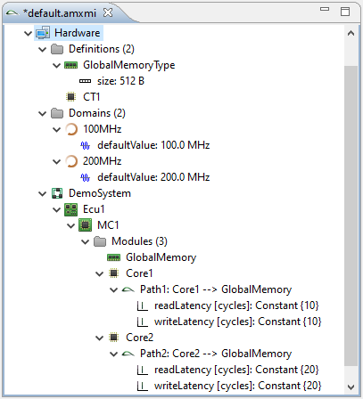
Optional: Feel free to add more memory elements to represent local memories
located at the cores with the proper latency access paths
At this point you should get a contents tree which looks like that:
Create simple OS model
Create a simple OS model, containing schedulers for both cores.
Right-click on the AMALTHEA model on the tree editor then select the menu item New Child > OS Model.
It will add a child node named Operating System to the model
Add a new operating system with name Default
- Select the Operating System node previously created
- Right-click on the item then select the menu item New Child > Operating Systems > Operating System.
- Name the created item Default
Add a Task Scheduler named Scheduler1
- Right-click on the Default operating system
then select the menu item New Child > Task Scheduler
- Name the created item Scheduler1
Add a standard OSEK scheduler definition
- Right-click on Operating System node
then select the menu item Create Model Structure > Scheduler Definition > Fixed Priority > OSEK
Add scheduler definition OSEK to Scheduler1
- Select the Scheduler1 task scheduler
then set the Definition property to OSEK
Add a Task Scheduler named Scheduler2
Add a scheduler definition OSEK to Scheduler2
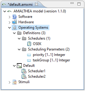
At this point you should get a contents tree which looks like that:
Add timing requirements for Tasks
Adding some deadline informations to the already created tasks.
Note: Doing this in a separate file, it can easy be reused for other models if the names of the tasks are the same!
Close the editor of file default.amxmi
- This is necessary because files of the same folder will be loaded when the first model is opened in the editor
Create a new AMALTHEA model “constraints.amxmi” in the same folder as the already created AMALTHEA meta model
- Select the folder model1 created during the paragraph General model setup
- Right-click on the mouse and select the menu item New > AMALTHEA Model
- Press Next to define the associated model file naming it constraints.amxmi
then press on Finish to create an empty model.
Right-click on the AMALTHEA model on the tree editor then select the menu item New Child > Constraints Model.
It will add a child node named Constraints to the model
Add a new Process Requirement named DeadlineTask1
- Select the Constraints item on the tree editor
- Right-click on the mouse and select the menu item New Child > Requirements > Process Requirement
- Name the created item DeadlineTask1
- Set the Process property to the value Task Task1
Add a Time Requirement Limit to “DeadlineTask1” Process Requirement
- Select the Process Requirement named DeadlineTask1 Task1
- Right-click on the mouse and select the menu item New Child > Limit > Time Requirement Limit
- Set the Limit Type property to UpperLimit
- Set the Metric property to ResponseTime
- Add limit to TimeRequirementLimit
- Right-click the mouse on the ResponseTime item and select the menu item New Child > Limit Value
- Set the Unit property of the new item to ms
- Set the Value property to 10
Add a new Process Requirement named DeadlineTask2 and set its Process property to the value Task Task2
Add a Time Requirement Limit to “DeadlineTask2” Process Requirement
- Set the Limit Type property to UpperLimit
- Set the Metric property to ResponseTime
- Add limit to the Time Requirement Limit
- Right-click the mouse on the ResponseTime item and select the menu item New Child > Limit Value
- Set the Unit property of the new item to ms
- Set the Value property to 15
Add a new Process Requirement named DeadlineTask3 and set its Process property to the value Task Task3
Add a Time Requirement Limit to “DeadlineTask3” Process Requirement
- Set the Limit Type property to UpperLimit
- Set the Metric property to ResponseTime
- Add limit to the Time Requirement Limit
- Right-click the mouse on the ResponseTime item and select the menu item New Child > Limit Value
- Set the Unit property of the new item to ms
- Set the Value property to 15
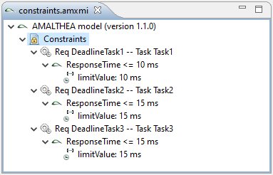
At this point your model should look like this:
The mapping represents which software elements are mapped to dedicated hardware elements.
Note: The mapping is separated into an extra file, which makes it easier to replace or change a mapping!
Close the editor of file constraints.amxmi
- This is necessary because files of the same folder will be loaded when the first model is opened in the editor
Create a new AMALTHEA model “mapping.amxmi” in the same folder as the already created AMALTHEA meta model
Right-click on the AMALTHEA model on the tree editor then select the menu item New Child > Mapping Model.
It will add a child node named Mapping to the model
Add a Scheduler Allocation element Scheduler1 -> Core1
- Right-click the mouse on the Mapping item and select
the menu item New Child > Scheduler Allocation
- Set the Scheduler property to Task Scheduler Scheduler1
- Set the Responsibility property to Processing Unit Core1
Add a Scheduler Allocation element Scheduler2 -> Core2
Add a Task Allocation element Task1 -> Scheduler1
set the Task to Task1 and the Scheduler to Scheduler1
Add a Task Allocation element Task2 -> Scheduler1
Add a Task Allocation element Task3 -> Scheduler2
Add a Memory Mapping at least for all Labels to map them to GlobalMemory
- Right-click the mouse on the Mapping item and select
the menu item New Child > Memory Mapping
- Set the Abstract Element property to Label LabelA
- Set the Memory property to Memory GlobalMemory
- Repeat the last 3 steps steps for the Label LabelB
Optional: If more memories are available, make a proper assignment to other memory elements.
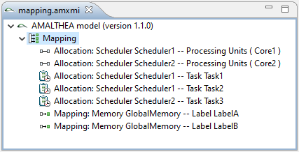
At this point your model should look like this:
Solution
The solution project for this exercise is available:
You can use the older model and migrate it to a newer version.