| Eclipse Corner Article |

Summary
Graphical Editing Framework (GEF) provides a powerful foundation for creating editors for visual editing of arbitrary models. Its effectiveness lies in a modular build, fitting use of design patterns, and decoupling of components that comprise a full, working editor. To a newcomer, the sheer number and variety of concepts and techniques present in GEF may feel intimidating. However, once learned and correctly used, they help to develop highly scalable and easy to maintain software. This article aims to provide a gentle yet comprehensive introduction to GEF. It describes a shape diagram editor - a small, fully functional test case of core concepts.
By Bo Majewski, Cisco Systems, Inc.
December 8, 2004
Graphical Editing Framework (GEF) has been designed to allow editing of user data, generally referred to as the model, using graphical rather than textual format. It becomes an invaluable tool when dealing with entities that contain many-to-many, one-to-many and other complex relationships. With the popularity of the Eclipse Rich Client Platform, which leads to development of editors for more than just code, the importance of GEF is certain to increase. A few existing examples, such as database schema editor [7], logical circuits editor, and a task flow manager nicely illustrate both the power and flexibility of the framework that may be applied to such varied and disparate domains.
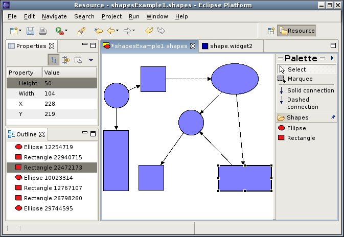
Yet the trouble with any generic framework, and GEF is no exception, is that its comprehensive design makes it hard to learn. Until recently, the smallest available example came with over 75 classes. Trying to understand nuances of GEF from interaction of that many user defined types and hundreds more native to GEF is certain to test the patience and acumen of even the most diligent developers. To rectify this issue, a new, much smaller example editor has been added and will appear in the upcoming 3.1 release. The shape diagram editor (see Figure 1) allows you to create and edit simple diagrams. It manipulates two types of objects, represented by rectangles and ellipses. You may connect any two objects with one of the two connection types. The two connection types are represented by solid and dashed lines. Each connection is directed, in the sense that it starts at a source object and terminates in the target object. The direction of each connection is indicated by an arrow. A connection may be reattached by dragging its source or target to a new object. Objects in the editor may be selected either by clicking on them or by dragging a rubber band around them. Selected objects can be deleted. All model manipulations, such as adding or deleting objects, moving them, resizing them, etc., may be undone or redone. Finally, the editor integrates with the Properties and Outline standard views of Eclipse. The editor's virtue comes not from its usefulness, but rather from the fact its limited number of user defined types serve as examples of a large percentage of concepts and techniques that one could encounter in a mature GEF editor.
 Download and unzip
the latest 3.1 GEF Examples from the
GEF Project
Downloads
into your main Eclipse directory. To create
a new diagram, launch the wizard by pressing Ctrl-N. Expand the
Examples folder and select Shapes Diagram. The following
sections give a detailed overview of the shape diagram inner workings. Before
we dive into code, let us start with a big picture tour of the main
GEF ideas.
Download and unzip
the latest 3.1 GEF Examples from the
GEF Project
Downloads
into your main Eclipse directory. To create
a new diagram, launch the wizard by pressing Ctrl-N. Expand the
Examples folder and select Shapes Diagram. The following
sections give a detailed overview of the shape diagram inner workings. Before
we dive into code, let us start with a big picture tour of the main
GEF ideas.
GEF assists you in building a visual editor of your data. The data may be
as simple as a thermostat with a single temperature knob, or as complex as a
virtual private network with hundreds of routers, connections, and quality of
service policies. To the credit of the GEF designers, they managed to create
a framework that works with any data, or in GEF terminology, with any model.
This is achieved by strictly following the Model-View-Controller pattern. The
model is your data. To GEF, a model is any plain old Java object. The model
should not know anything about either the controller or the view. The view
is the visual representation of the model or one of its parts on the screen.
It may be as simple as a rectangle, line or ellipse, or as complex as a nested
logical circuit. Again, the view should remain ignorant about both the model
and the controller. GEF uses Draw2D figures as views, although anything that
implements the IFigure interface will do. The controller, known
as an edit part, is the one that brings the two together. A top level
controller is created when you start editing your model. If the model consists
of many fragments, the top level controller informs GEF about that fact. In
turn, child controllers for each fragment are created. If those again consists
of subparts, the process is repeated until all objects that comprise a model
have their controllers built. The other task of the controller is to create
a figure representing the model. Once the model has been set on a particular
controller, the GEF asks it for the congruous IFigure object. Since
neither the model nor the view know about each other, it is the task of the
controller to listen to changes in the model and update the visual representation
of it. As a result, a common pattern in many GEF editors is a model that posts
PropertyChangeEvent notifications. When an edit part receives an
event notification it reacts appropriately by adjusting visual or structural
representation of the model.
Another aspect of visual editing is reacting to user actions and mouse or keyboard events. The challenge here is to provide a mechanism that comes with sensible defaults, yet at the same time is flexible enough to allow those defaults to be replaced by interactions appropriate for the edited model. Take a mouse drag event as an example. If we were to assume every time a mouse drag event is detected that all selected objects are moved, we'd limit the freedom of the editor developer. It is quite likely that somebody might wish to provide zoom in or out operations on a mouse being dragged. GEF solves this issue by using tools, requests, and policies.
A tool is a stateful object that translates low level events,
such as mouse pressed, mouse dragged, and so on, into high level
requests, represented by a Request object.
Which request is posted depends on which tool is active. For example,
the connection tool, upon receiving a mouse pressed event, posts a
connection start or connection end request. If it was a create tool,
we'd receive a create request. GEF comes with a number
of predefined tools and means of creating application specific
tools. Tools may be activated programmatically or as a response to a
user action. Most of the time, tools post requests to the EditPart
whose figure was underneath the mouse. For example, if you click on a rectangle
representing a widget, the edit part associated with it receives a
selection or direct edit request. Sometimes, like the MarqueeSelectionTool
does, the request
is posted to all parts whose figures are contained within a given area. Regardless of
how one or more edit parts are chosen as the target of requests,
they do not handle requests themselves. Instead, they delegate this
task to registered edit policies. Each policy is asked for a command
for a given request. A policy not wishing to handle the request may
return a null. The mechanism of having policies
rather than an edit part respond
to requests allows to keep both of them small
and highly specialized. This, in turn, means easy to debug and more
maintainable code.
The final piece of the puzzle is commands. Rather than
modifying the model directly, GEF requires that you do it with the help of
commands. Each command should implement applying and undoing
changes to the model or its part. This way GEF editors automatically
support the undo/redo of model alterations.
A significant benefit of using GEF, in addition to being able to boast about
your skills and design pattern knowledge, is the fact that it fully
integrates with the Eclipse platform. Objects selected in the editor
may provide properties for the standard Properties view. Eclipse wizards
may be used to create and initialize models edited by GEF editors. Undo
and Redo items of the Edit menu may trigger undoing or redoing of
GEF editing changes. Simply put, GEF editors are first class citizens
of the regular Eclipse platform, with the same level of integration as
a text editor or any other workbench editor, implementing IEditorPart
interface.
The first step when building a GEF editor is to create a model. In our case the model consists of four types of objects: a shape diagram, which holds shapes, two shape types, and shape connections. Before we start writing code for those classes, we prepare some basic infrastructure.
When creating a model use the following guidelines:
java.beans package.
As the above outlined rules are common for all models, it is beneficial
to create a hierarchy of base classes that enforces them. The
ModelElement extends Java's Object class, adding
three features: persistence, property change, and property source support.
Simple model persistence is guaranteed by implementing
![]() the
the
java.io.Serializable interface together with
![]() the
the
readObject method. This solution permits one to save the
editor's model in a binary
format. While it may work for certain applications, it does not provide
format portability. In more complex cases, one may implement
saving the model in XML or similar format. Model changes are communicated
using property change events. The base class allows edit parts to
![]() register and
register and
![]() unregister as receivers of property change notifications.
Those are posted by calling
unregister as receivers of property change notifications.
Those are posted by calling
![]() the
the firePropertyChange method.
Finally, in order to aid integration with the Properties view of the workbench,
![]() the
the IPropertySource interface is implemented (details of which
are omitted in Figure 2).
public abstract class ModelElement implementsIPropertySource,
Serializable { private transient PropertyChangeSupport pcsDelegate = new PropertyChangeSupport(this);
public synchronized void addPropertyChangeListener(PropertyChangeListener l) { if (l == null) { throw new IllegalArgumentException(); } pcsDelegate.addPropertyChangeListener(l); }
protected void firePropertyChange(String property, Object oldValue, Object newValue) { if (pcsDelegate.hasListeners(property)) { pcsDelegate.firePropertyChange(property, oldValue, newValue); } }
private void readObject(ObjectInputStream in) throws IOException, ClassNotFoundException { in.defaultReadObject(); pcsDelegate = new PropertyChangeSupport(this); }
public synchronized void removePropertyChangeListener(PropertyChangeListener l) { if (l != null) { pcsDelegate.removePropertyChangeListener(l); } } ... }
Two types of objects, ellipse and rectangle shapes, share further common
functionality that may be factored out into a common class. In particular,
both represent objects that occupy certain locations and have a non-zero
size. Both may have connections ending or originating at them. Any changes
to these properties need to be communicated to all listeners. Furthermore,
the location and size property are also exposed through the
IPropertySource interface, allowing the user to inspect and
modify them via the Properties view.
Management of connections between objects is worth a more detailed look.
There is no concept of a global store of all connections. Instead, GEF
requires model parts to report any connections that start
or terminate in them. These must be reported as Lists
of objects. The Shape class maintains two array lists
of ![]() source and
source and
![]() target connections. The source connections are those
which have the given shape as the source, and target connections
are those in which the given shape is recorded as the target. Two
methods
(
target connections. The source connections are those
which have the given shape as the source, and target connections
are those in which the given shape is recorded as the target. Two
methods
(![]() ,
,
![]() ),
with package level visibility, are added that allow shapes
and connections to communicate about their mutual relationship. In
addition, two public methods
(
),
with package level visibility, are added that allow shapes
and connections to communicate about their mutual relationship. In
addition, two public methods
(![]() ,
,
![]() )
are defined that allow classes external
to the
)
are defined that allow classes external
to the model package learn about connectivity of a shape.
These are used by shape controllers, explained in the subsequent part
of this article.
public abstract class Shape extends ModelElement {

    private Point location = new Point(0, 0);
    private Dimension size = new Dimension(50, 50);
 private List sourceConnections = new ArrayList();
 private List targetConnections = new ArrayList();

    public Point getLocation() {
        return location.getCopy();
    }

    public void setLocation(Point newLocation) {
        if (newLocation == null) {
            throw new IllegalArgumentException();
        }
        location.setLocation(newLocation);
        firePropertyChange(LOCATION_PROP, null, location);
    }

 void addConnection(Connection conn) {
        if (conn == null || conn.getSource() == conn.getTarget()) {
            throw new IllegalArgumentException();
        }
        if (conn.getSource() == this) {
            sourceConnections.add(conn);
            firePropertyChange(SOURCE_CONNECTIONS_PROP, null, conn);
        } else if (conn.getTarget() == this) {
            targetConnections.add(conn);
            firePropertyChange(TARGET_CONNECTIONS_PROP, null, conn);
        }
    }

 void removeConnection(Connection conn) {
        if (conn == null) {
            throw new IllegalArgumentException();
        }
        if (conn.getSource() == this) {
            sourceConnections.remove(conn);
            firePropertyChange(SOURCE_CONNECTIONS_PROP, null, conn);
        } else if (conn.getTarget() == this) {
            targetConnections.remove(conn);
            firePropertyChange(TARGET_CONNECTIONS_PROP, null, conn);
        }
    }

 public List getSourceConnections() {
        return new ArrayList(sourceConnections);
    }

 public List getTargetConnections() {
        return new ArrayList(targetConnections);
    }

    ...
}
With the above preparation we may start coding top level model classes.
The Connection class represents a connection between two
shapes. It stores the source and target of a connection. Changes in
connectivity are effected by invoking disconnect or
reconnect methods. Connections maintain a boolean
flag indicating if they are currently connected or disconnected.
The flag is used by commands to verify legitimacy of certain
operations. Both source and target retain
references to the original shapes allowing disconnected connections
to be easily reconnected. Connections maintain one attribute,
the line style. The EllipticalShape and
RectangularShape classes
provide an extension to the above described Shape
class, with a minimum of functionality added.
The ShapeDiagram class extends the ModelElement
class with the container functionality. It maintains a collection of
shapes and notifies listeners about collection changes. The boolean values
returned by ![]() the
the addChild and
![]()
removeChild methods
are used by commands to perform validation of their operations. Public access to all
shapes in a diagram is ![]() provided for the benefit of the controller class.
provided for the benefit of the controller class.
public class ShapesDiagram extends ModelElement {

    ...
    private Collection shapes = new Vector();

 public boolean addChild(Shape s) {
        if (s != null && shapes.add(s)) {
            firePropertyChange(CHILD_ADDED_PROP, null, s);
            return true;
        }
        return false;
    }

 public List getChildren() {
        return new Vector(shapes);
    }

 public boolean removeChild(Shape s) {
        if (s != null && shapes.remove(s)) {
            firePropertyChange(CHILD_REMOVED_PROP, null, s);
            return true;
        }
        return false;
    }
}
ShapeDiagram - a container
of shapes
A careful reader is certain to recognize that the model effectively created a specific implementation of a directed graph, with shapes acting as vertices, connections representing edges, and shape diagrams playing the role of the graph. The representation built here is known as adjacency list representation and is suitable for sparse graphs. With minimal effort, one could transform the model's code into a generic graph representation. The only additions to the implementation regularly presented in books on algorithms is the fact that the graph, its nodes, and its edges post events when their states change. Also nodes, unlike in mathematical graphs, rather than being zero-dimensional points, have rectangular bounds. Finally, while regular graphs act as a central global storage of edges, a diagram does not hold connections, as GEF does not require it.
It is worth noting that the solutions employed by the above presented classes are not the only ones possible. Those who developed computer representations of graphs may prefer alternative ways of storing connections or arranging communications between nodes and edges. However, such details are not important. Designers are free to choose their own more generic, faster, or otherwise enhanced model representation. The vital part is event based notification of model changes, maintenance of all, including visual attributes of the model, and support for model persistence. Depending on your experience and needs, the rest are traits which you should feel free to alter.
Due to the simplicity of the shape diagram editor, we do not have to create figures
representing our model, but use predefined figures instead. A
diagram is represented by the Figure class equipped with the
FreeformLayout manager. This gives
us the freedom to drag and drop objects at any location. Objects
are represented either by the RectangleFigure or
by Ellipse. Relying on predefined figures to represent parts of
the model is uncustomary. Even though your view may not have any
references to either the model or the controller, it must have a
visual attribute for every important aspect of the model that the
user may wish to inspect or change. It is thus much more common
to define intricate figures with the number of visual attributes,
such as color, text, nested figures, etc., matching the number
of attributes of the model they represent. For a more
thorough treatment about creating complex figures please see
[4].
For each independent piece of the model we must define a controller. By "independent" we mean an element that may be subject to user manipulations. A good rule of thumb to follow is that anything that may be selected or deleted should have its own edit part.
The role of edit parts is to understand the model, listen to events about
its changes, and update views, correspondingly. Due to the choices made
at the model level, all edit parts follow the pattern shown in
Figure 5. Each part ![]() implements the
implements the PropertyChangeListener
interface. When ![]() activated, it registers with the model as the receiver of
the property change events. Upon
activated, it registers with the model as the receiver of
the property change events. Upon
![]() deactivation, it removes itself from the
list of listeners. Finally, when it
deactivation, it removes itself from the
list of listeners. Finally, when it
![]() receives a property change event, based
on the name of the property and the new and old values it refreshes one
or more visual aspects of the figure representing the model. In fact, this
pattern is so common that in a larger application it would justify creating
a base class factoring out this behavior.
receives a property change event, based
on the name of the property and the new and old values it refreshes one
or more visual aspects of the figure representing the model. In fact, this
pattern is so common that in a larger application it would justify creating
a base class factoring out this behavior.
public abstract class SpecificPart extends AbstractGraphicalEditPart
When the editor successfully loads and sets a shape diagram object on a
graphical viewer, the ShapesEditPartFactory is asked to
create a part controlling the diagram. It creates a new DiagramEditPart
and sets the diagram as its model. The newly created part is activated,
registers itself with the model, and creates a figure, with a free form layout
manager that allows positioning of diagram figures based on their constraints
(bounds). The DiagramEditPart reports all shapes contained
in the diagram via the getModelChildren. As mentioned before,
GEF repeats the process of generating parts and figures for all returned
model children.
The DiagramEditPart class installs three policies. All policies
should be installed in the createEditPolicies method that
is declared by the AbstractEditPart class, and must be implemented
by all concrete classes extending the AbstractGraphicalEditPart.
Policies are delegates used by edit parts to handle requests posted by
tools. In the simplest cases, policies take care of generating
commands. A policy is registered with the String key, referred
to as the policy's role.
The key has no meaning to edit parts. However, it should have meaning to a software
developer, as it allows others, specifically those who extend your
controller, to disable or remove the policy by specifying its key. As far
as GEF is concerned, your key could be "foobar". However,
you'd better tell your fellow developers that in order to, say, set a new
layout policy when the layout manager is changed, they need to
install a new "foobar" policy. As this might be amusing, but not
obvious, it is recommended that you use keys defined in
the EditPolicy interface, whose names
try to convey the role the given policy plays in an edit part.
The ![]() first policy installed using the
first policy installed using the EditPolicy.COMPONENT_ROLE key
has the task of preventing the root of the model from being deleted. It overrides
the createDeleteCommand method to return an unexecutable
command. The ![]() second policy, installed with the
second policy, installed with the LAYOUT_ROLE
key, handles create and constraint change requests. The first request is
posted when a new shape is dropped into a diagram. The layout policy
returns a command that adds a new shape to the diagram editor and places
it at the drop location. The constraint change request is posted whenever
the user resizes or moves shapes already present in the diagram. The
![]() third call to the
third call to the installEditPolicy removes rather than
installs a policy. This prevents the root part from providing selection
feedback when the user clicks on the area of the diagram corresponding
to the root of the model. This call also illustrates the importance of
meaningful keys used to register part's policies.
protected void createEditPolicies() {
 installEditPolicy(EditPolicy.COMPONENT_ROLE, new RootComponentEditPolicy());
    XYLayout layout = (XYLayout) getContentPane().getLayoutManager();
 installEditPolicy(EditPolicy.LAYOUT_ROLE, new ShapesXYLayoutEditPolicy(layout));
 installEditPolicy(EditPolicy.SELECTION_FEEDBACK_ROLE, null);
}
The diagram edit part monitors child added and child removed property events.
These are posted by the ShapesDiagam class whenever new
shapes are added or removed. Upon detecting either type of a property
change event, the diagram edit part invokes the refreshChildren
method, defined in the AbstractEditPart. This method traverses
all model children and creates, removes, or re-orders edit part children
appropriately.
Diagram shapes are managed by the ShapeEditPart. The part itself
is created by the ShapesEditPartFactory in response to
DiagramEditPart returning a list of model children. Each
part created by the factory is given the child model which it controls.
Once the model is set, the part is asked to create a figure representing it.
Depending on the type of the model, it returns either an ellipse or a
rectangle.
Shape edit parts monitor four types of property change events: size,
location, source, and target connections. If the shape changes size or location,
the ![]()
refreshVisual method is called. This method is automatically
invoked by GEF the first time a figure is created. In it, the visual
attributes of the figure should be adjusted based on the state of the
model. Reusing the same method for model updates is another frequently
encountered pattern in GEF editors. In the case of the shape editor part,
the new location and size are fetched and stored with the figure representing
the shape. In addition, the new bounds are passed as the constraint to the
layout manager of the parent controller. When source or target connections
change, the source or target connection edit parts are refreshed by a call
to the methods defined in the AbstractGraphicalEditPart.
Similarly to the refreshChildren method, these methods go
through the list of connections and add, remove, or reposition edit parts
corresponding to them.
class ShapeEditPart extends AbstractGraphicalEditPart
As shapes may be connected to other shapes, the shape edit part overrides the
![]()
getModelSourceConnections and the
![]()
getModelTargetConnections methods. The role of these methods
is to inform GEF about connections that originate or terminate at the
given shape. In addition, the ShapeEditPart implements
the ![]()
NodeEditPart interface. By implementing it, the edit part is
able to define source and target anchors, i.e., points to which connections
attach. The logic circuit editor example uses this feature to indicate
where a wire would attach to a logical gate. Since shapes do not have
any specific connection points, we use a chop box anchor which clips the
connection against the rectangular bounds of the figure. If you wish,
you can return the EllipseAnchor for ellipse shapes, which
returns a point on the ellipse's boundary. For more complex shapes, you should
extend the AbstractConnectionAnchor class and implement the
getLocation method. Notice that two types of methods are
implemented: one taking a ConnectionEditPart, and one
taking a Request as the parameter. The
![]() second method is invoked to provide a user with feedback while a new
connection is being created. The
second method is invoked to provide a user with feedback while a new
connection is being created. The
![]() first one is used for
established connections.
first one is used for
established connections.
Shape edit part installs two policies. The ShapeComponentEditPolicy
supplies a command for removing a shape from the diagram. The second policy,
installed with the GRAPHICAL_NODE_ROLE key, handles the task of
creating and reattaching connections between shapes. A new connection is
created in two steps by the connection creation tool. When a user clicks on a
figure corresponding to an element of the model, the policy is requested to
![]() create a connection command. Returning
create a connection command. Returning null from this method
indicates that the connection may not originate from the given element of
the model. If the connection is possible, a new command should be created and
stored in the request as the start command. When another figure is
clicked, the policy is required to supply a
![]() connection complete command. This
could be a new command built from the start command, or the start command tag
supplied with the information about the terminating point of the connection.
connection complete command. This
could be a new command built from the start command, or the start command tag
supplied with the information about the terminating point of the connection.
new GraphicalNodeEditPolicy() {
 protected Command getConnectionCreateCommand(CreateConnectionRequest request) {
       Shape source = (Shape) getHost().getModel();
       int style = ((Integer) request.getNewObjectType()).intValue();
       ConnectionCreateCommand cmd = new ConnectionCreateCommand(source, style);
       request.setStartCommand(cmd);
       return cmd;
    }

 protected Command getConnectionCompleteCommand(CreateConnectionRequest request) {
        ConnectionCreateCommand cmd =
            (ConnectionCreateCommand) request.getStartCommand();
        cmd.setTarget((Shape) getHost().getModel());
        return cmd;
    }

    ...
}
The other task of the graphical node edit policy is to provide connection
reattachment commands. Connection reattachment may change the source or the
target of the connection. The same rules apply to these commands as to the
connection creation command. In particular, if a given connection should not
be reattached, the policy must return null. It is also possible for the policy
to return a command that refuses to be executed, by returning false from the
canExecute method. Due to space limitation, details of these
commands are left out and the reader is referred to the source code.
As connections are user editable parts of the model, they
must have their own controller. It is implemented
by the ConnectionEditPart class, which extends
the AbstractConnectionEditPart
class. Similar to other controllers, it implements the
![]()
PropertyChangeListener interface
and registers the part for the events with the model on activation.
The connection part
![]() returns a polyline decorated with an arrow as the figure.
It installs two edit policies. The
first one, the
returns a polyline decorated with an arrow as the figure.
It installs two edit policies. The
first one, the ![]()
ConnectionComponentPolicy, supplies
a delete command needed by the action associated with the Delete
menu item. The ![]() second one is of greater interest. It equips
a selected connection with handles, placed at the start and the
end. Without this policy, reattaching connections
is impossible, as the GEF has no handles to grab onto when the
end of the connection is being dragged. The authors of the GEF
recommend that all
second one is of greater interest. It equips
a selected connection with handles, placed at the start and the
end. Without this policy, reattaching connections
is impossible, as the GEF has no handles to grab onto when the
end of the connection is being dragged. The authors of the GEF
recommend that all ConnectionEditParts should have
this policy, even if their ends are not draggable. At minimum this
policy provides a visual selection feedback. The
propertyChange method watches for
![]() changes in the line
style property and adjusts the polyline figure appropriately.
changes in the line
style property and adjusts the polyline figure appropriately.
class ConnectionEditPart extends AbstractConnectionEditPart
The shape editor extends the GraphicalEditorWithFlyoutPalette
class. This class is a specialized form of a graphical editor, a type
of an editor part, equipped with a palette hosting tool entries. The
extending class must implement two methods, getPaletteRoot
and getPalettePreferences. The first method must return a
palette root populated with tool entries. Tool entries are specialized
types of palette entries capable of installing tools on the edit
domain of the editor. They may be hosted in palette drawers, which
provide convenient way of grouping them. It is recommended that
one tool entry is set as the default entry of the palette root. A typical
solution is to use an instance of the SelectionToolEntry
class in that role. Palette preferences, returned by the second method,
specify whether the palette is visible or collapsed, the location where it
is docked, and the palette width. A commonly found solution is to save them
to and restore them from the plug-in's preference store.
The already mentioned edit domain plays the role of a central controller. It
holds a palette of tools, loads the default tool, maintains the active tool
to which it forwards mouse and key events, and deals with the command stack.
GEF provides the default implementation, the DefaultEditDomain,
which you should set on your editor in the constructor.
Part of the job that a graphical editor must perform is to create and
initialize a graphical viewer. A graphical viewer is a specialized
EditPartViewer capable of performing hit testing. Again, we may
rely on the default viewer supplied by the
GraphicalEditor class. There are, however, a few things that
need to be done. In the configureGraphicalViewer method
![]() set a factory of edit parts. The factory must implement
the sole method of the
set a factory of edit parts. The factory must implement
the sole method of the EditPartFactory interface,
createEditPart(EditPart, Object). The first argument is the
edit part that returned the second argument, a (part of your) model, through
the getModelChildren method. Other things to do here
may include setting up a key handler, context menus, etc.
protected void configureGraphicalViewer() {
    super.configureGraphicalViewer();

    GraphicalViewer viewer = getGraphicalViewer();
    viewer.setRootEditPart(new ScalableRootEditPart());
 viewer.setEditPartFactory(new ShapesEditPartFactory());
    viewer.setKeyHandler(
        new GraphicalViewerKeyHandler(viewer).setParent(getCommonKeyHandler()));
    ContextMenuProvider cmProvider =
        new ShapesEditorContextMenuProvider(viewer, getActionRegistry());
    viewer.setContextMenu(cmProvider);
    getSite().registerContextMenu(cmProvider, viewer);
}

protected void initializeGraphicalViewer() {
    super.initializeGraphicalViewer();
    GraphicalViewer graphicalViewer = getGraphicalViewer();
 graphicalViewer.setContents(getModel());
 graphicalViewer.addDropTargetListener(createTransferDropTargetListener());
}
Once the factory is set, you should
![]() set the contents on the graphical viewer.
The contents naturally should be the object restored from the
set the contents on the graphical viewer.
The contents naturally should be the object restored from the
IEditorInput passed to the editor in the setInput
method. The shape example also adds
![]() a drop target listener to the graphical
viewer. This allows one to use the drag and drop gesture rather than select and
click when adding new shapes to the diagram. The drop target listener
uses a subclassed
a drop target listener to the graphical
viewer. This allows one to use the drag and drop gesture rather than select and
click when adding new shapes to the diagram. The drop target listener
uses a subclassed TemplateTransferDropTargetListener that
uses a CreateRequest to fetch a command for adding an
object to the model owned by the edit part above which the drag and
drop gesture was finalized.
In addition to the described tasks, the editor takes care of reporting
the dirty flag by monitoring a command stack. This is a preferred
solution, as this keeps the flag in synch with any undo or redo
actions that the user may perform. Notice that the command stack
has the save location marked in both doSave and
doSaveAs methods. Other details of the editor, such
as actual saving and restoring of the model, are not discussed here
as they tend to be very application specific. The editor's functionality
that deals with exposing editor content to other views, connecting
menu items to editor actions, and other workbench cooperation techniques
is described next.
The editor, as presented so far, would be fully operational. However, it would not integrate well with the workbench. For example, the Edit menu actions, such as Delete, Undo, and Redo could not be used. Other views could not show alternative presentations of the editor content. In other words, the editor would not get the benefits of being part of the Eclipse workbench. The task of transforming an isolated editor into a proper participant of the workbench is explained in the following three sections.
The ShapesEditor class creates a number of default
actions in the createActions method invoked during editor
initialization. These are undo, redo, select all, delete, save, and print
actions. In order to
connect standard menu items to them, you should define an action bar
contributor and list it, in the plugin.xml file, as
the editor contributor. In the action bar contributor you need to
implement two methods. The first one,
![]() the
the buildActions method,
should create retargetable actions for undo, redo, and delete. If you
wish to enable keyboard selection of all widgets, you need
to ![]() add a global
action key for the selected action in the second method,
add a global
action key for the selected action in the second method,
declareGlobalActionKeys.
public class ShapesEditorActionBarContributor extends ActionBarContributor {
 protected void buildActions() {
        this.addRetargetAction(new UndoRetargetAction());
        this.addRetargetAction(new RedoRetargetAction());
        this.addRetargetAction(new DeleteRetargetAction());
    }

    public void contributeToToolBar(IToolBarManager toolBarManager) {
        super.contributeToToolBar(toolBarManager);
        toolBarManager.add(getAction(ActionFactory.UNDO.getId()));
        toolBarManager.add(getAction(ActionFactory.REDO.getId()));
    }

    protected void declareGlobalActionKeys() {
     this.addGlobalActionKey(ActionFactory.SELECT_ALL.getId());
    }
}
It may be illustrative to trace what happens when the user selects
the Delete item in the Edit menu (see Figure 12). The
delete action, which is added to the action registry by the
parent class of the ShapesEditor class, traces the
current selection. When the delete action is executed, it checks
if any of the currently selected objects are instances of the
EditPart class. For each such object it requests a command
from the edit part. In turn, each edit part checks if any of the
edit policies created on it understand and are willing to handle
the delete request. For shapes, the ShapeComponentEditPolicy
claims it can handle the delete request, and when asked for a command
it returns a ShapeDeleteCommand instance. The
action executes the command, which removes the shape from
the diagram. The diagram fires a property change event that is
handled by the DiagramEditPart and ultimately leads to
a rectangle or ellipse representing the deleted shape to be removed from the
display.
Every graphical editor is a source of selection events. You can test this
by creating a view that registers with the workbench site's page as a selection listener.
Every time you select an object in your graphical editor, your view
receives a notification in the selectionChanged method. One
of Eclipse's standard views, Properties view, listens to
selection events, and for every selection checks if its objects implement
the IPropertySource interface. If so, it uses the methods of
the interface to interrogate the selected object or objects about their
properties and displays them in a tabular format.
Thanks to the above described infrastructure, exposing properties of objects
edited in graphical editor is a matter of implementing methods of the
IPropertySource interface. By inspecting the Shape
class you can view how position and size of objects are made
available to the Properties view.
The Outline view is used to provide an alternative and often more succinct view of edited data. In Java editors it is used to show imports, variables, and methods of the edited class, without going into code details. Graphical editors can also benefit from such a high level view. The shape diagram editor, similarly to the logic circuit editor, exposes the edited contents in the form of a tree (see Figure 1). The database schema editor [7] provides a view of the entire editor window with a thumb for panning.
In order to expose edited content to the Outline view, you need to
override the getAdapter method and
![]() return an outline
implementation when the adapter class is the
return an outline
implementation when the adapter class is the IContentOutlinePage
interface. The easiest way to implement an outline is to extend
the ContentOutlinePage class by supplying it with an
appropriate configured EditPartViewer.
public Object getAdapter(Class type) {
    // returns the content outline page for this editor
 if (type == IContentOutlinePage.class) {
        if (outlinePage == null) {
            outlinePage = new ShapesEditorOutlinePage(this, new TreeViewer());
        }
        return outlinePage;
    }
    return super.getAdapter(type);
}
In the case of the shape diagram editor, the edit part view is implemented by
a tree viewer. You should supply it with the same edit domain as your
main editor. A tree viewer, just like any other EditPartViewer,
requires a method for creating child edit parts. The editor uses the same
mechanism as that employed with the DiagramEditPart, by
setting an edit part factory on it. In addition, the selection of the
overview and the main editor window is synchronized using a
selection synchronizer, a GEF utility class that reconciles the selection
state of two edit parts. The ShapesTreeEditPartFactory
returns either a ShapeTreeEditPart or a
DiagramTreeEditPart instance, depending on the model type. By
inspecting those classes, the reader should have no difficulty recognizing
already familiar patterns. Both edit parts implement the
PropertyChangeListener interface and react to property changes
by adjusting visual representation of the model. Both install edit policies
to control types of interactions exposed through them.
GEF attains its flexibility through an extensive use of design patterns. Provided here is a brief summary of those most commonly encountered. For a more detailed treatment on patterns please see [2].
Object.
The view must implement the IFigure interface. The controller
is a type of an EditPart.
Commands which then
are chained together.
createChild allows you to explicitly create child
edit parts without using a factory.
I tried giving a detailed description of most aspects of a very simple
graphical editor. Hopefully there is enough information provided to allow
anybody patient enough to read this lengthy essay to inspect larger examples,
such as the logic circuit editor.
By immediately understanding roles of classes such as
CircuitEditPart, AndGateFigure, and a few others
that directly correspond to classes present in the simple shape editor,
you may focus your attention on more complex aspects of larger examples.
There exists a plethora of subjects and techniques in GEF whose surface I have not
even scratched. However, they should be studied only after the base is
well understood. After all, what is the purpose of trying to design
a drag feedback, if it takes you a few hours to enable the Select All
menu item?
I would like to thank Randy Hudson for his comments that helped improve the structure and accuracy of this article. My thanks also go to Jill Sueoka for tirelessly reviewing numerous versions that I managed to produce.
| [1] | Eric Bordeau, Using Native Drag and Drop with GEF, Eclipse Corner Article, August 2003 |
| [2] | Erich Gamma, Richard Helm, Ralph Johnson and John Vlissides, Design Patterns: Elements of Reusable Object-Oriented Software, Addison Wesley, 1995, ISBN 0-201-63361-2 |
| [3] | Randy Hudson, Create an Eclipse-based application using the Graphical Editing Framework, IBM developerWorks, July 2003 |
| [4] | Daniel Lee, Display a UML Diagram using Draw2D Diagram, Eclipse Corner Article, August 2003 |
| [5] | Xavier Mehaut et al., Synthetic GEF description, June 2004 |
| [6] | William Moore, David Dean, Anna Gerber, Gunnar Wagenknecht and Philippe Vanderheyden, Eclipse Development using the Graphical Editing Framework and the Eclipse Modeling Framework, IBM RedBooks, 2004, ISBN 0738453161 |
| [7] | Phil Zoio, Building a Database Schema Diagram Editor with GEF, Eclipse Corner Article, September 2004 |
Java and all Java-based trademarks and logos are trademarks or registered trademarks of Sun Microsystems, Inc. in the United States, other countries, or both.